
Changing the Phase Distance
When planning cable ampacity, the combination of conductor heat losses and sheath/screen heat losses typically accounts for the majority of the total heat losses in a cable. Changing the phase distance and bonding system will affect these losses.
Solid Bonded System
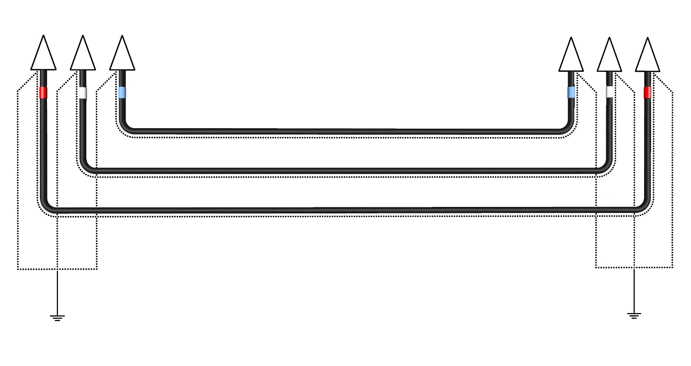
Section titled “Solid Bonded System”For solid bonding of the sheath/screen, e.g. two-point bonded systems, the presence of circulating currents elevates the net heat loss in cable considerably. The circulating currents will increase with increasing phase distance, again reducing the cable ampacity.
Single-point Bonded System
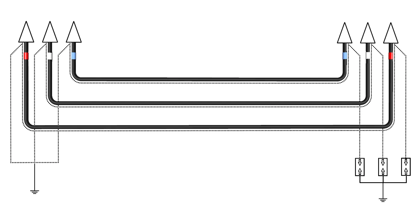
Section titled “Single-point Bonded System”For single-point bonded system, the cables are bonded at one end, and the circulating currents will not flow in the screen/sheath, although a voltage will be induced in the screen/sheath based on the length of the cable. The absence of circulating currents allows for higher current capacity through the conductor and increasing the phase distance does not add circulating-current losses the way it does in a solid bonded system.
Calculations in Grøft Design®
Section titled “Calculations in Grøft Design®”To calculate the effect of changing the phase distance the following project was made in Grøft Design®:
| Parameter | Value |
|---|---|
| Cable | TSLF 3x1x1600 mm² |
| Depth | 0.7 meter |
| Conductor Zone | 350 mm @ 1 m.K/W |
| Backfill Zone | 550 mm @ 2.5 m.K/W |
| Surrounding Masses | 2.5 m.K/W |
| Ground Temperature | 15 °C |
| Phase Distance/Configuration | Varying* |
| Bonding | Single-point or solid bonding system |
*The simulation included the following Phase Distance/Configuration:
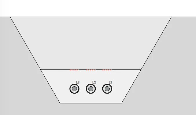
- Trefoil formation
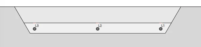
- Flat formation with 0 mm phase distance
- Flat formation with 70 mm phase distance
- Flat formation with 150 mm phase distance
- Flat formation with 300 mm phase distance
- Flat formation with 500 mm phase distance
- Flat formation with 750 mm phase distance
- Flat formation with 1000 mm phase distance
- Flat formation with 1500 mm phase distance
- Flat formation with 2000 mm phase distance
Screenshots of the trench in Grøft Design®:
Ampacity
Section titled “Ampacity”As shown in Table 1, for a solid bonded system, ampacity decreases as the phase distance increases. This is due to the increasing screen/sheath currents and associated losses. The most significant impact occurs between 0-300 mm distance, and the effect decreases from 300 and beyond. This is because the increased distance between phases allows for more heat dissipation cancelling out some of the effects of the increased screen/sheath current/losses.
In Table 1, for the single-point system, the ampacity increases as the phase distance increases, which is the opposite of the effect seen in solid bonded systems. This occurs because single-point bonding prevents circulating currents in the screen/sheath, eliminating their associated losses. The increased phase distance allows for improved heat dissipation, resulting in a higher cable ampacity.
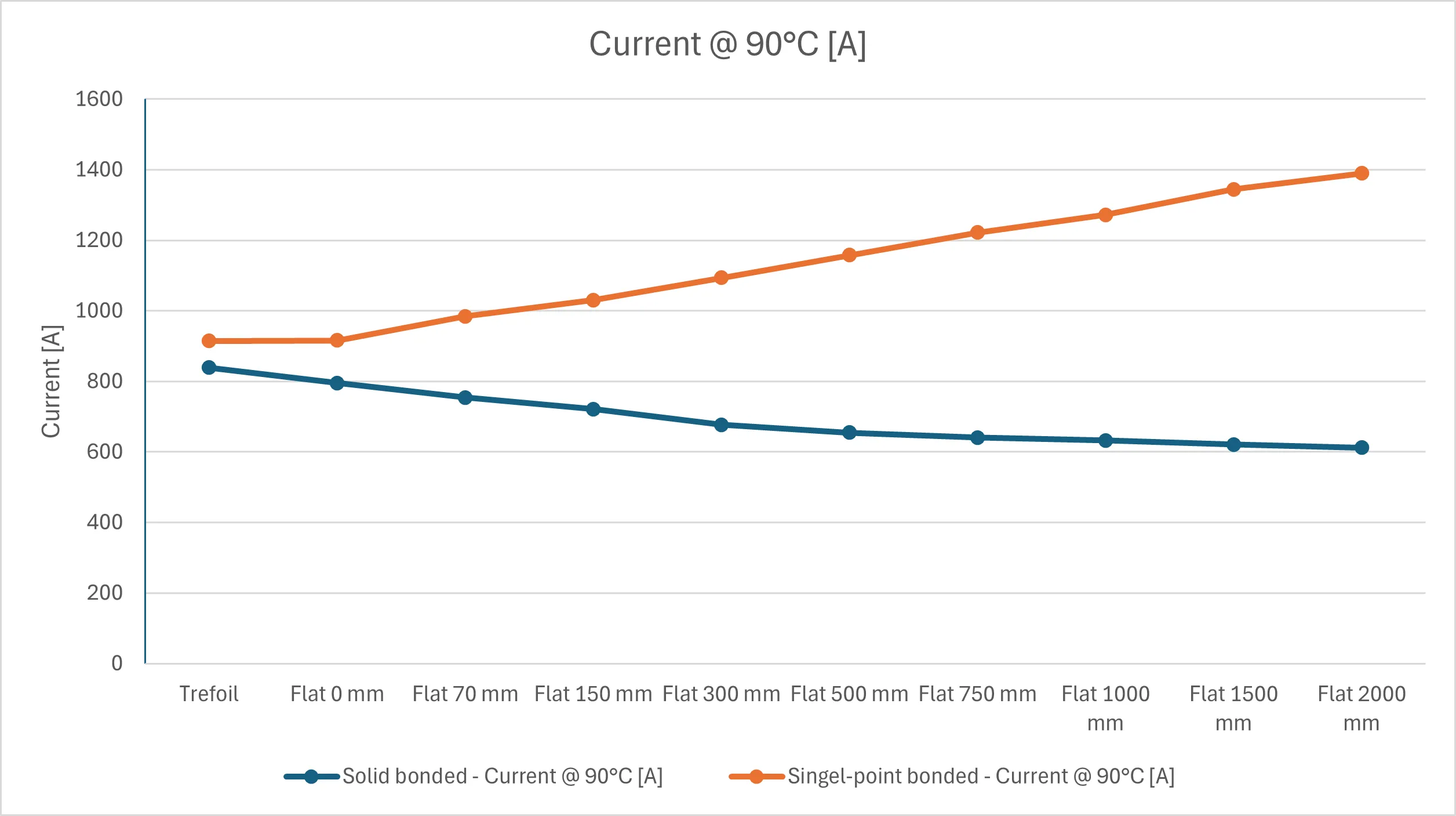 Table 1: Solid bonded cable and Single-point bonded current at 90 °C conductor temperature
Screen/Sheath Current and Voltage Rise
Section titled “Screen/Sheath Current and Voltage Rise”As shown in Table 2, the screen/sheath current increases with greater phase distance, leading to higher heat losses.
In Table 2, screen/sheath losses are not presented, as they are limited to eddy currents rather than circulating currents. However, in a single-point bonded system, the voltage rise along the cable must be considered, particularly the standing voltage at the unbonded end. This voltage, expressed in V/km, increases with phase distance. To mitigate this, a surge voltage limiter (SVL) is typically installed at the unbonded end.
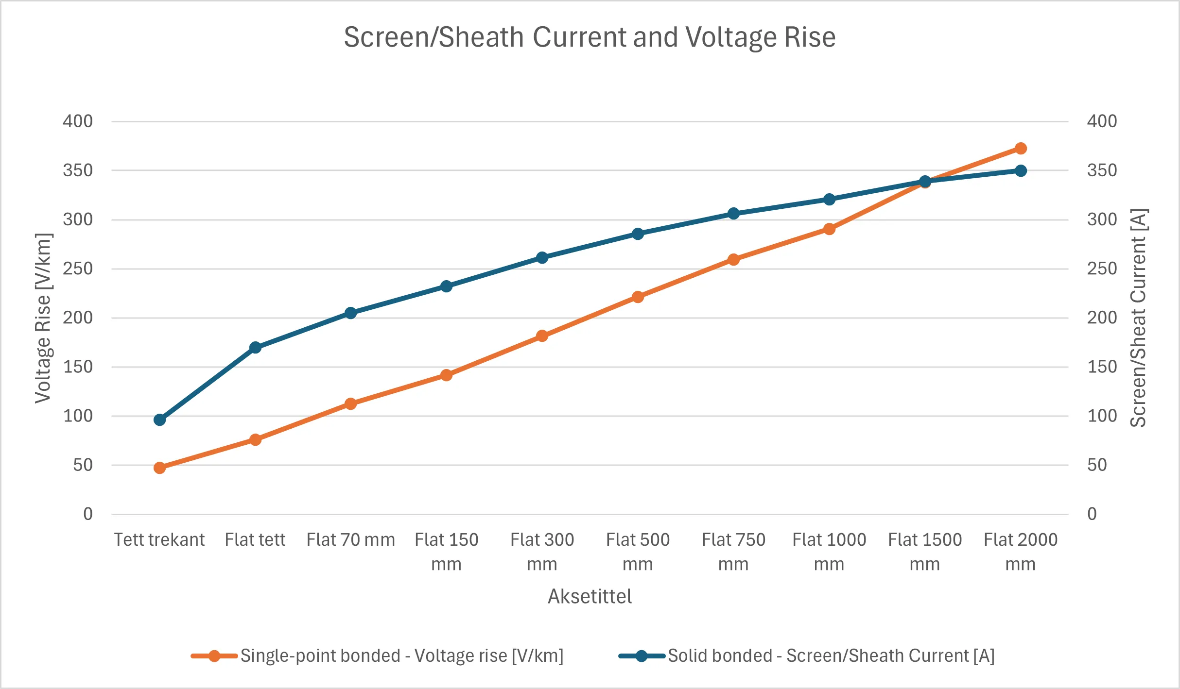 Table 2: Screen/sheath current and voltage rise
Magnetic Field
Section titled “Magnetic Field”In both bonding systems, the magnetic field intensity increases with greater phase distance.
In this example, the single-point bonded system generates a higher magnetic field overall, as expected. Magnetic field strength is proportional to current, and the single-point bonded system has higher ampacity and current capacity as phase distance increases. In contrast, the solid bonded system experiences decreasing ampacity and current with increasing phase distance.
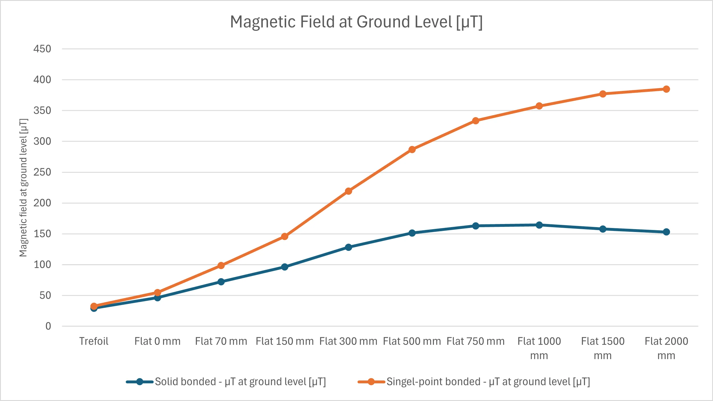 Table 3: Magnetic field at ground level