
Release Log
Release 2026 September
Section titled “Release 2026 September”Cable Burial Below Seabed (Subsea Scenario)
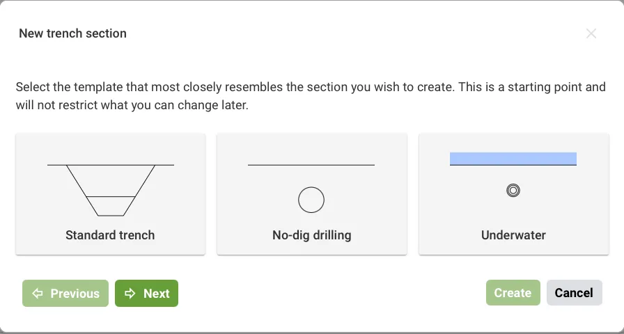
Section titled “Cable Burial Below Seabed (Subsea Scenario)”In Subsea scenarios, cables can now be modeled buried beneath the seabed.
Filtering in Trench Cross-Section List
Section titled “Filtering in Trench Cross-Section List”The Trench Cross-Section list can now be filtered by keyword, making it easier to find specific cross-sections in large projects with many trench cross-sections.
Temperature Probes
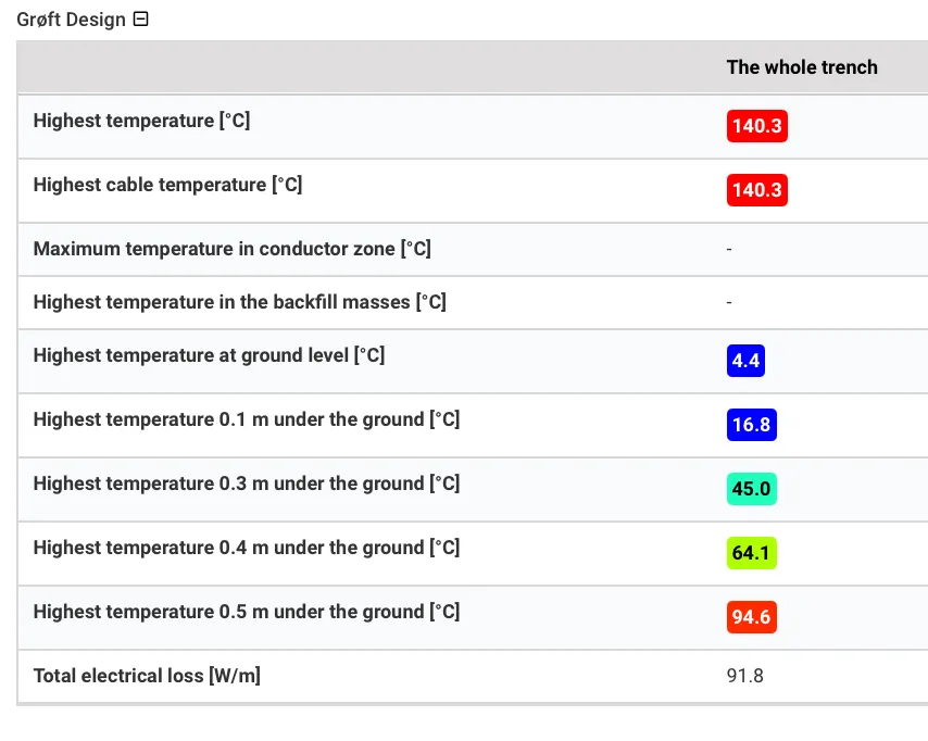
Section titled “Temperature Probes”Added linear probes for evaluating the maximum temperature at specified depths in the ground or seabed surrounding cable installations. Use them to verify compliance with environmental or regulatory temperature-rise limits, including 2 K criterion check.
Full Convection (CFD) for Advanced Users
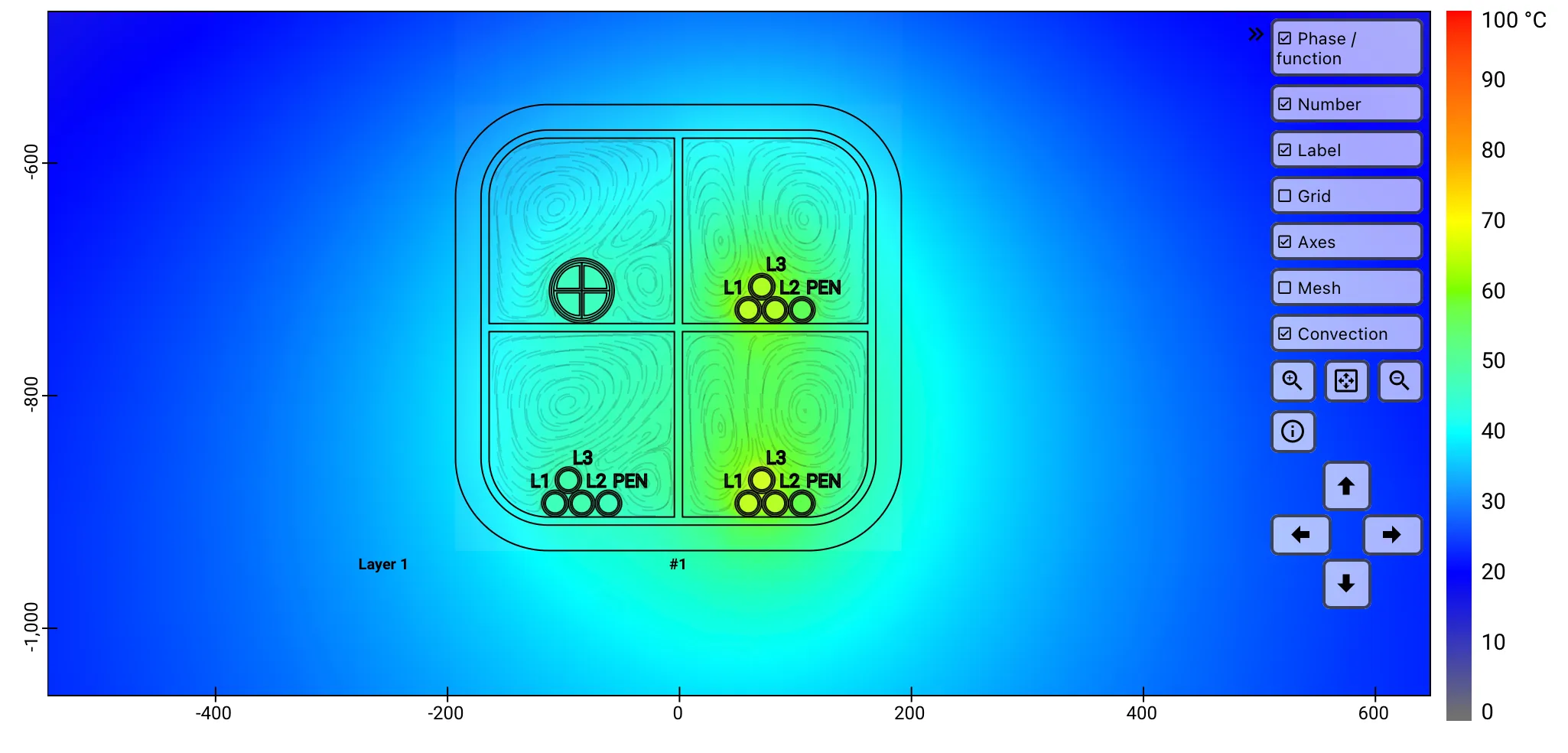
Section titled “Full Convection (CFD) for Advanced Users”For Advanced User license, added simulations of buoyancy-driven natural convection around cables installed in enclosed air-filled spaces, coupled with conductive and radiative heat-transfer modelling.
Maximum Temperature Displayed for All Objects
Section titled “Maximum Temperature Displayed for All Objects”Every object placed in the trench cross-section now shows its maximum achieved temperature in the results list.
Release 2026 June
Section titled “Release 2026 June”Permissible Short-circuit Current per IEC 60949
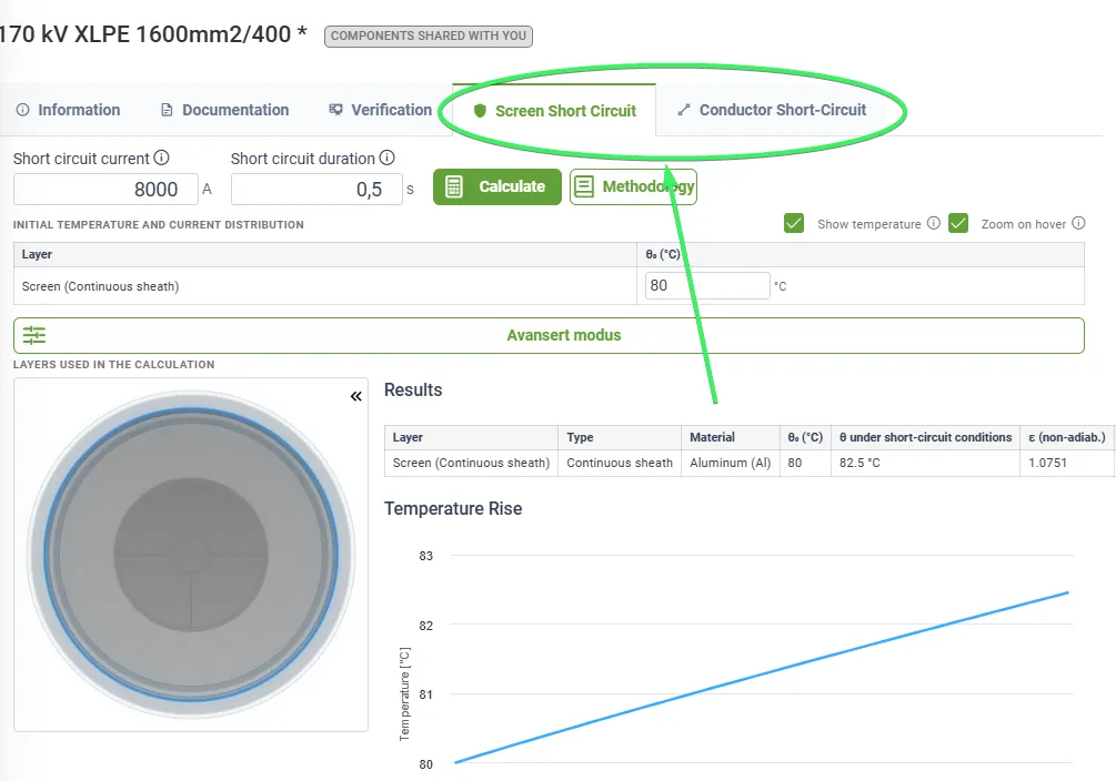
Section titled “Permissible Short-circuit Current per IEC 60949”Grøft Design® now calculates the permissible short-circuit current for cables in accordance with IEC 60949, making it easier to verify cable ratings under fault conditions. For more information, click here
Multi-way Duct
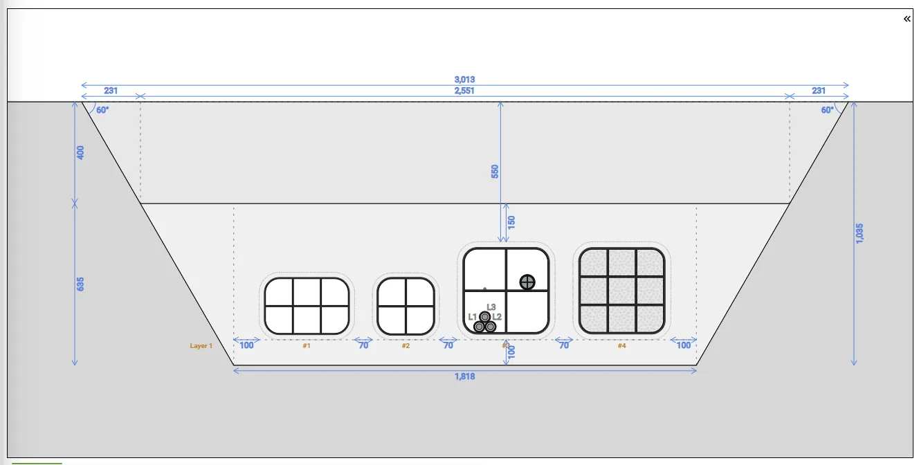
Section titled “Multi-way Duct”Multi-way cable protection ducts are now available as a duct type. A multi-way duct is a single prefabricated unit with multiple separate bores, allowing several cables to share one duct — reducing trench width and simplifying installation in congested corridors.
Predefined configurations are available for Melbye’s product range (4-way, 4-way XL, 6-way, and 9-way), and custom geometries can be defined for other manufacturers or project-specific requirements.
Note: Ampacity calculations for multi-way ducts assume conductive heat transfer only. Users without access to the full convection module will receive conservative results.
Custom Items Database
Section titled “Custom Items Database”Custom items can now be saved directly to the component database, making them reusable across projects and accessible to your whole team. For more details, click here
Automatic Cable/Item Placement in Custom Item
Section titled “Automatic Cable/Item Placement in Custom Item”Cables and items are now automatically placed in cavities on custom items, enabling the use of drag and drop and reducing the need for “free placement”.
Release 2026 May
Section titled “Release 2026 May”Sheath Standing Voltage
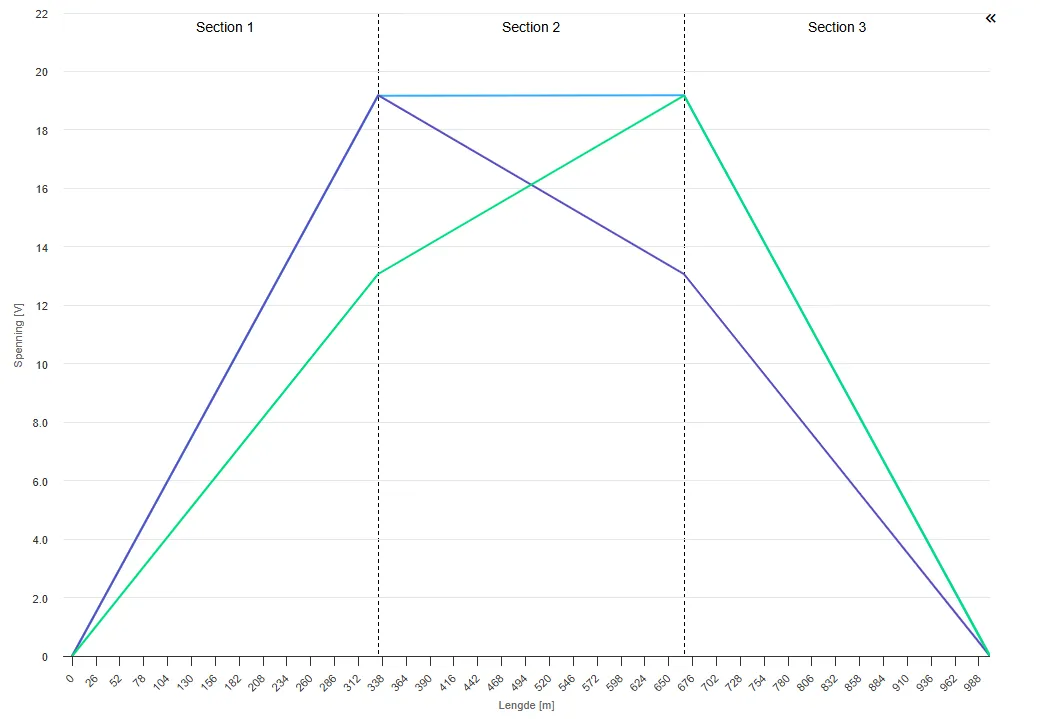
Section titled “Sheath Standing Voltage”For cross-bonded and single-point bonded systems, the voltage rise in the cable sheaths is presented as a plot on the results page. To generate the plot for a single-point bonded system, the trench cross-section length must be specified.
Other Changes
Section titled “Other Changes”Some other minor changes and fixes have been implemented.
Release 2026 March
Section titled “Release 2026 March”Default Threshold for Dry-out Zone
Section titled “Default Threshold for Dry-out Zone”The threshold for dry-out zone in the software is assumed as default to 50 °C, according to IEC 60853-3. The default value is changed from 60 °C to 50 °C.
Fix for Conductor Resistance Display
Section titled “Fix for Conductor Resistance Display”We identified a discrepancy in how conductor resistance was fetched and displayed in the Grøft Design® UI. The FEM simulation reports the total terminal resistance, which includes minor coupling effects from induced currents in surrounding metallic screens. This value was previously shown in the UI instead of the intended conductor-only resistance.
The UI now correctly displays the pure conductor resistance rather than the full terminal resistance reported by the simulation.
This was a display-only issue. Model calculations—including losses and temperatures—were always correct. No simulation results are affected.
Release 2026 February
Section titled “Release 2026 February”Cyclic Load (24h) as Initial Value
Section titled “Cyclic Load (24h) as Initial Value”Users can now apply the 24-hour cyclic load as the initial value for variable load calculations.
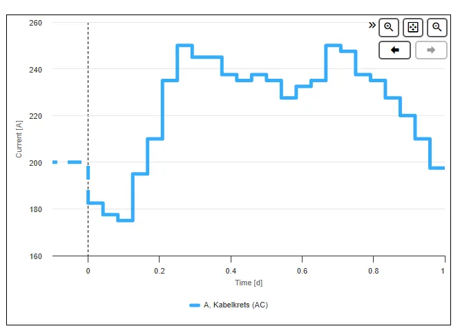
New Visualization of Load Before Time 0
Section titled “New Visualization of Load Before Time 0”A new graphical view has been introduced to display load conditions prior to time 0, providing better insight into initial states.
Export Trench Cross-Sections to CAD (DXF Format)
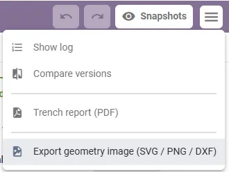
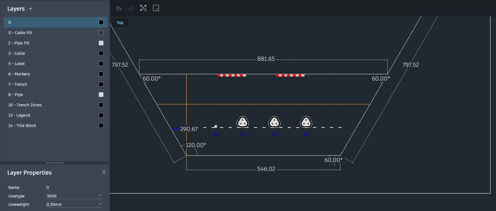
Section titled “Export Trench Cross-Sections to CAD (DXF Format)”It is now possible to export trench cross-sections directly to CAD in DXF format. This allows for seamless integration with external design tools and simplifies coordination with engineering drawings.
Other Changes
Section titled “Other Changes”Some other minor changes and fixes have been implemented.
Release 2026 January 2
Section titled “Release 2026 January 2”Utilize the Same Cable for Both AC and DC Circuits
Section titled “Utilize the Same Cable for Both AC and DC Circuits”Cables can now be tagged for use in both AC and DC circuits, eliminating the need to duplicate cables to support both AC and DC with the same cable.
Support for Variable Load Initial State Scenarios
Section titled “Support for Variable Load Initial State Scenarios”Initial state selection is no longer limited to only steady-state scenarios. Variable load scenarios can now be used as initial states. In this setup, the initial state scenario is executed first, and the analysed scenario starts from the exact temperatures and conditions reached at the end of the initial state scenario. Note: This approach increases simulation time, as the full initial state scenario is always run in addition to the analysed scenario.
Comsol Upgrade
Section titled “Comsol Upgrade”The underlying COMSOL engine has been upgraded to COMSOL Multiphysics 6.4.
Release 2026 January
Section titled “Release 2026 January”DC Cable Rating
Section titled “DC Cable Rating”Support for Direct Current (DC) cable systems has been introduced. This covers the following critical aspect for cable rating studies:
- Ampacity Constraints: Rating of DC cables against both thermal limitations and insulation constraints (maximum temperature drop over the insulation).
- Dynamic Rating: Time-dependent load profiles enable dynamic rating of DC cables, allowing for optimized dimensioning based on actual load cycles rather than worst-case steady-state assumptions.
- Interface of AC and DC: Calculation of the thermal interaction between AC and DC cables installed in the same trench or duct bank. The software simulates the electromagnetic and thermal effects in AC, while assuming pure ohmic loss in DC, to account for the mutual heating effect which derates adjacent AC/DC installations.
DC simulation has been validated against CIGRE Technical Brochure 880 (Power Cable Rating Examples for Calculation Tool Verification), specifically Case Study 7: A 320 kV HVDC submarine bipole. The added support for DC:
- Aligns with the emerging shift from point-to-point HVDC to multi-terminal and hybrid distribution networks (CIGRE Technical Brochure 875). Converting AC lines to DC can increase power capacity by 57% to 88% using the same conductor cross-sections. The new functionalities in Grøft Design® allow users to quantify this specific gain for their projects.
- Allows Grøft Design® users to model hybrid grid situations where DC links are embedded within existing AC infrastructure.
- Provides the necessary simulation tools to design the complex, multi-feeder trenches required for future power grids.
- Supports workflows described in the recently released CIGRE Green Book on High Voltage DC Transmission Systems (December 2025). Specifically, addressing the need for precise thermal dimensioning in high-load HVDC corridors.
Cable Armor
Section titled “Cable Armor”It’s now possible to model cables with armor. If the armor is magnetic and of a wired construction, then simulation of trenches that contain AC circuits will currently not include all armor losses. Results will be presented with a clear warning about this omission. These additional losses will be included in a future release.
Thermal Resistivity
Section titled “Thermal Resistivity”Thermal resistivity of polypropylene has been changed from 7.14 to 5.9 K.m/W. Thermal resistivity of water blocking tape has been changed from 10 to 12 K.m/W. These changes are made to better align with recommended values (Ineos and TB 880). Simulation results for trench sections containing e.g. polypropylene pipes might be affected with a temperature difference of up to 1-2 degrees Celsius.
Changes to Load Factor Scenarios
Section titled “Changes to Load Factor Scenarios”Changes have been made to simulations including 24h load factors. The 6h ramp-up is now a step function rather than a linear increase. This aligns with IEC recommendations and will have a minor impact on the result. Support for inputing loss factor rather than load factor has been added and simulation results now include maximum temperatures from all cables.
Free Cable Phase Selection
Section titled “Free Cable Phase Selection”Circuits no longer require strict rules for cable phases. This means that you can now create e.g. 3 single phase circuits and map them separately to L1, L2 and L3, effectively creating your own custom three phase circuit. With that, you can for example apply unbalanced currents.
Other Changes
Section titled “Other Changes”- When adding a cable, the default operating voltage will now be the cable insulation level rather than the closest standard operating voltage. Nothing will happen to your existing projects.
- Improvements have been made to how results are read in dynamic load scenarios.
- Some other minor changes and fixes have been implemented.
Release 2025 October
Section titled “Release 2025 October”Cross Bonding of Cable Shield or Screen
Section titled “Cross Bonding of Cable Shield or Screen”You can now simulate cable routes with cross-bonded shields/sheaths. Grøft Design® supports modeling of a cross-bonded major section composed of three successive, geometrically equal, minor sections with the same or variable lengths.
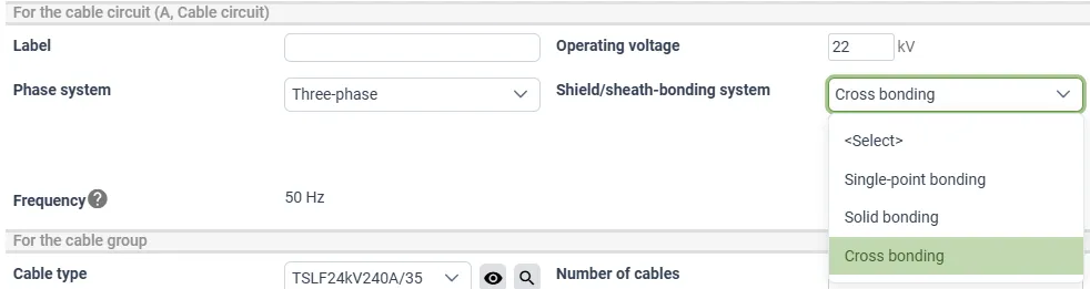
For more details on cross bonding, click here
Magnetic Field Shielding Calculations
Section titled “Magnetic Field Shielding Calculations”Simulations for magnetic field mitigation using metal structures (magnetic constructions) are now available in Grøft Design®.
For more details, please refer to the feature page and assumptions and limitations.
Screen Wires in the Cable Filler
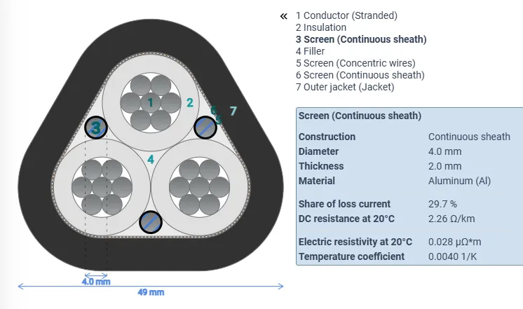
Section titled “Screen Wires in the Cable Filler”Screen wires (and more) in cable filler were supported before, but now this support includes compacted cables.
Code Optimizations and Bug fixes
Section titled “Code Optimizations and Bug fixes”This release also includes code optimizations for faster configuration of the FEM-model and reduced overhead in normal use. Plus some bug fixes.
Release 2025 June
Section titled “Release 2025 June”Extended Configuration Options for Disconnected Cable Circuits
Section titled “Extended Configuration Options for Disconnected Cable Circuits”A cable circuit that is not connected and energized can be in one of three idle connection states. The previous versions only support that you could specify 0 A for valid circuits, and incomplete circuits automatically became grounded at both ends. Now, the user has full control over the three idle connection states. This is configured under the simulation tab.
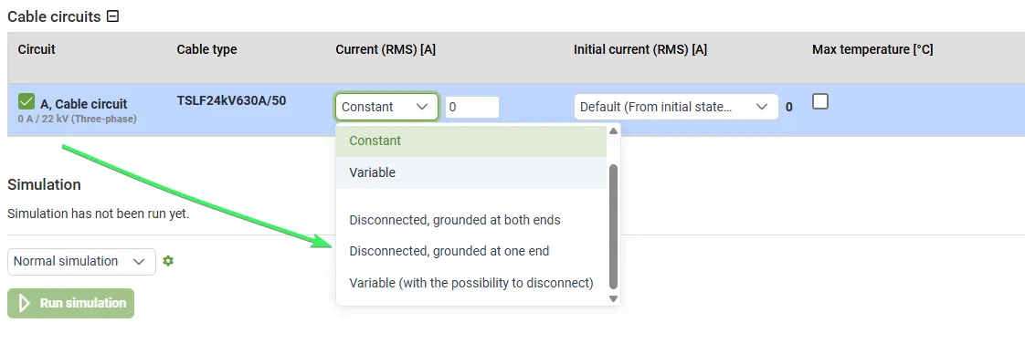
Disconnected, Grounded at One End
Section titled “Disconnected, Grounded at One End”The cables are disconnected and the ground system is connected with the conductors at one end. No current flows through the conductors, but a voltage may be induced. There are no dielectric losses in the insulation.
Disconnected, Grounded at Both Ends
Section titled “Disconnected, Grounded at Both Ends”The cables are disconnected and the ground system is connected with the conductors at both ends. There is no voltage in the conductors, but a current may be induced. There are no dielectric losses in the insulation.
Connected, with a Specified Current of 0 A
Section titled “Connected, with a Specified Current of 0 A”No-load conditions where cables are connected and energized under system voltage. Dielectric losses in the insulation are present, however no load-related resistive losses, for example due to charging current, will be considered in the cable.
The cables are connected and under system voltage, but no current flows through the conductors. The cables exhibit dielectric losses in the insulation since the cable is energized.
Support for Single Phase and Two-phased Cable Circuits
Section titled “Support for Single Phase and Two-phased Cable Circuits”You can now create and simulate cable circuits using single phase and two-phased systems. Two-core cable configurations are now supported in the Cable Designer.
Phases Exposed for Multicore Cables
Section titled “Phases Exposed for Multicore Cables”To support circuits with varying numbers of phase conductors and different phase angles, phase mapping and selected results are now available for each core.
Changed Convention for Phase Ordering
Section titled “Changed Convention for Phase Ordering”In previous versions of Grøft Design®, the ACB convention (L1-L3-L2) for the phases was used in a three phase system. This has now been changed to the more widely used ABC convention (L1-L2-L3).
Upgraded UI
Section titled “Upgraded UI”The user interface framework has been upgraded. There are some minor changes in visual appearance.
Release 2025 May
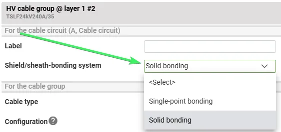
Section titled “Release 2025 May”Shield/sheath-bonding system
Section titled “Shield/sheath-bonding system”The configuration option for closed / open screen has been renamed “shield/sheath-bonding system” with the options “single-point bonding” and “solid bonding”. The objective of this change is to enhance clarity and to facilitate the implementation of a cross-bonding option in the future.
PNG and report optimization
Section titled “PNG and report optimization”A new software component is now utilized for rendering PNG images, significantly improving rendering performance. This enhancement will be noticeable during report generation, as most reports include numerous PNG images.
New zoom behavior
Section titled “New zoom behavior”With this new behavior, scrolling the mouse wheel over an image will only trigger zooming when the user also holds down the Ctrl, Shift, or Meta key. This change gives users full control over zoom functionality and helps prevent unintentional zooming.
The previous zoom behavior can still be enabled via a configurable user setting.
Improved permeability modelling
Section titled “Improved permeability modelling”For hysteresis losses to be accurately accounted for, permeability must be specified as a complex number. This is accomplished by introducing a new material property “Magnetic Loss Tangent”.
Material property overrides
Section titled “Material property overrides”The process for assigning and overriding material properties has been streamlined. This most notably affects custom pipes and custom items.
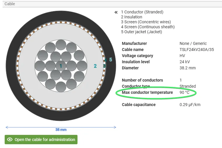
Maximum (allowed) conductor temperature
Section titled “Maximum (allowed) conductor temperature”The maximum (allowed) conductor temperature for a cable has always been available; however, it is now presented more clearly when selecting a cable in the cross-section , and a warning is issued in the results for cables where this temperature is exceeded.
Release 2025 March
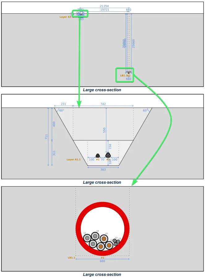
Section titled “Release 2025 March”Improvement for Large Trench Cross-sections
Section titled “Improvement for Large Trench Cross-sections”The size limitations for trench cross-sections have been significantly raised. The maximum distance between trenches and the maximum depth has been increased to 100 meters. In order to make such large trench cross-sections more manageable, images in reports and exports now support multiple views where needed. For example, reports for a cross-section with deep drilling can include both overview images including measures for drilling depth and images zoomed in at the drilling location. The same applies for two trenches with a significant distance between each other.
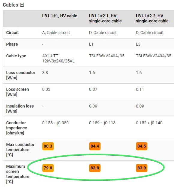
Screen Temperature is Included in the Results
Section titled “Screen Temperature is Included in the Results”The maximum screen temperature is now included in the results for each cable with a screen. This can be useful e.g. for comparing simulated temperatures versus actually measured temperatures from sensors placed among the screen wires.
Possibility to Add Cables/pipes from the Corresponding Tabs
Section titled “Possibility to Add Cables/pipes from the Corresponding Tabs”You can now add cables directly from the cables tab, and pipes from the pipes tab.
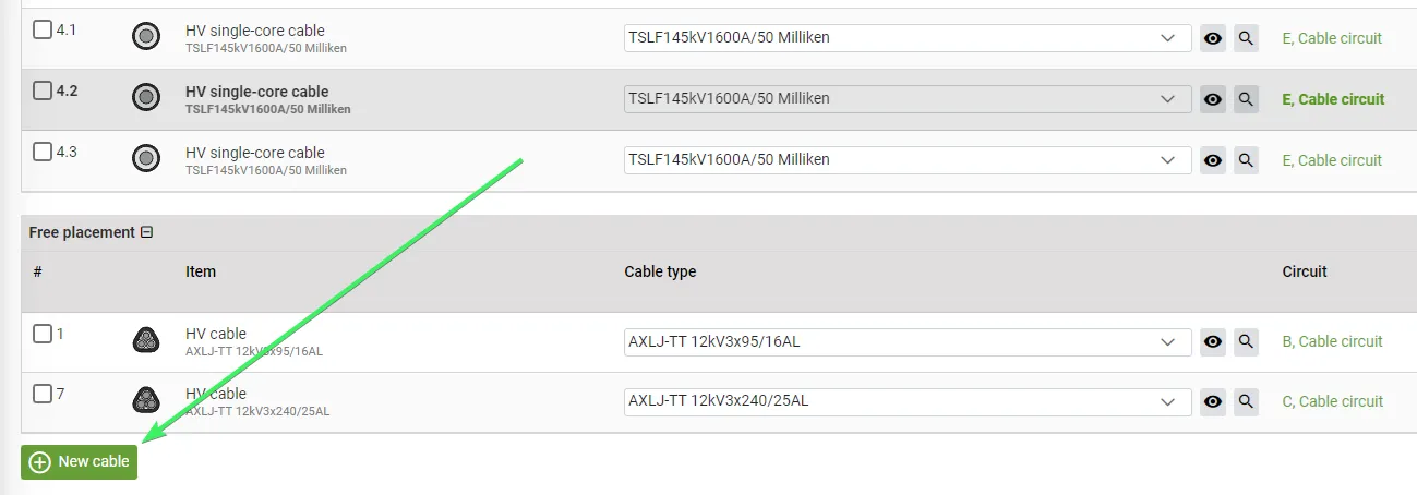
Usability Improvements for Objects with “Free placement”
Section titled “Usability Improvements for Objects with “Free placement””Objects can now be inserted or pasted directly to specific areas outside of layers. Moving or duplicating objects with free placement objects inside them now treat those objects as part of the wrapping object.
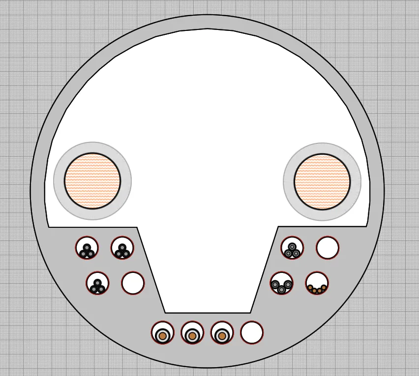
Possibility to Place Cables on Top of Custom Objects
Section titled “Possibility to Place Cables on Top of Custom Objects”It was previously possible to place “free placement” objects inside the fill geometries of a custom object. Now you can also place them inside the main area of the custom object. This makes it easier to e.g place pipes inside custom objects without first creating fill geometries and then aligning the pipes with them.
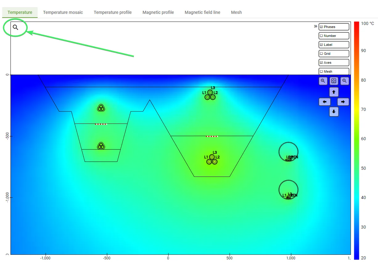
Visual Alternative for Activating/Deactivating Interactive Zoom
Section titled “Visual Alternative for Activating/Deactivating Interactive Zoom”For better control over when the mouse wheel is captured by an image, a magnifying icon has been added to the top left of images. Clicking it forces activation or deactivation of the image. (The escape key and clicking outside of the image can still be used for deactivation.)
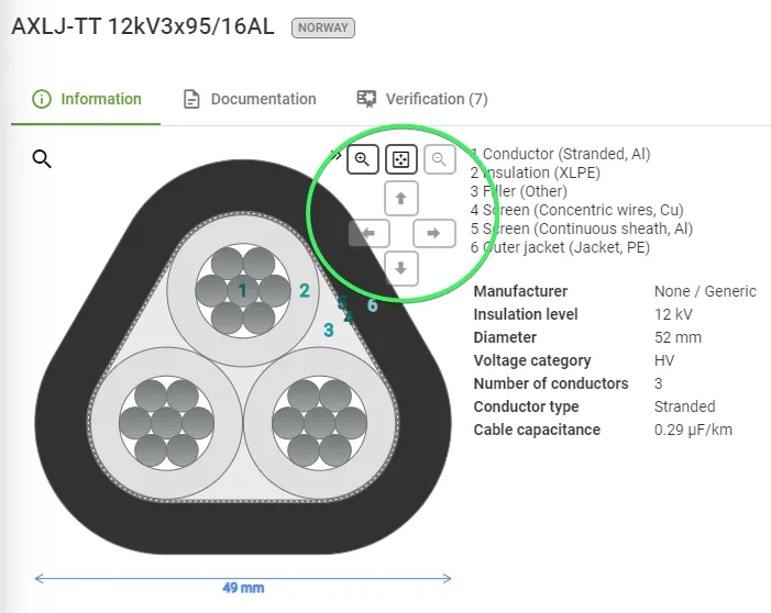
Visual Controls Added to Cable Images
Section titled “Visual Controls Added to Cable Images”The cable image shown when selecting or editing a cable has been enhanced with similar controls as the trench images. This includes buttons for zooming and resetting the view and the icon for activating and deactivating the image.
Highlighting Components with Documentation and Verifications
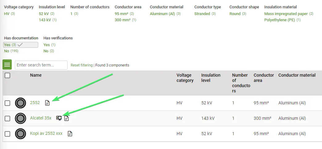
Section titled “Highlighting Components with Documentation and Verifications”In the component lists, icons have been added to show which components have documentation and / or verifications. These lists can also be filtered based on those criteria.
Flat Cable Layout Support Removed
Section titled “Flat Cable Layout Support Removed”This option caused confusion e.g. when adding cable groups to pipes. A better option is most of the time to separate the cable group into separate cables and position these freely. If a strict flat layout is needed, then it can be accomplished using custom layout.
Outdated Simulations Flagged in the Scenario List
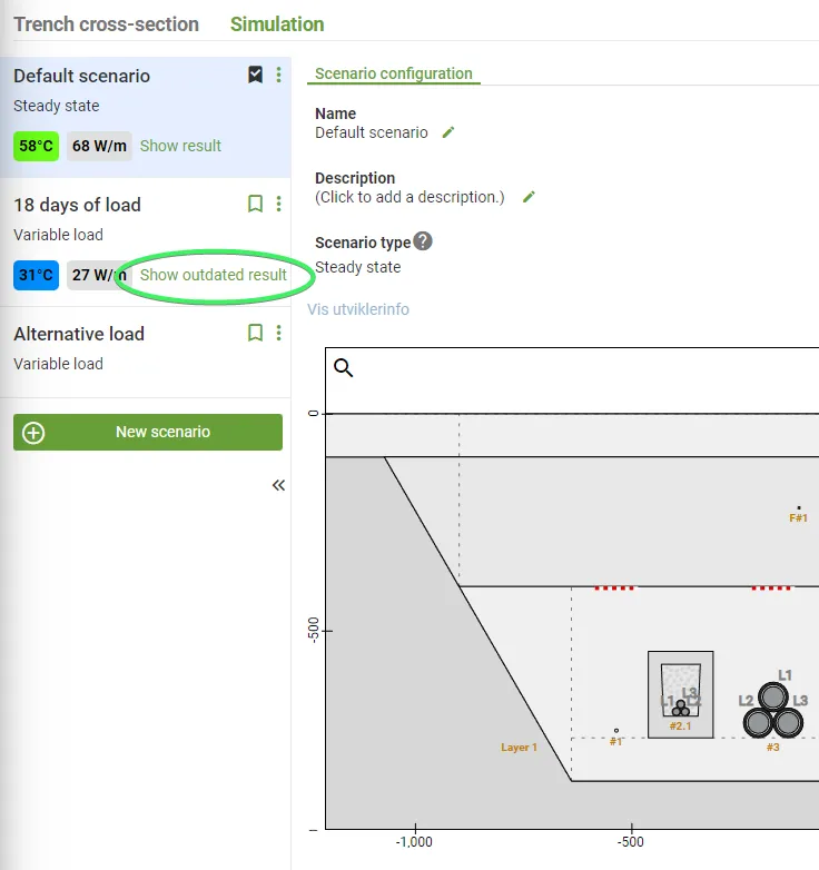
Section titled “Outdated Simulations Flagged in the Scenario List”To keep the scenario list concise, outdated simulations are indirectly pointed out by the wording “Show outdated result”.
Improved Accuracy for Quick Simulation in Dynamic Load Scenarios
Section titled “Improved Accuracy for Quick Simulation in Dynamic Load Scenarios”The chart for temperature over time could contain some unexpected spikes when run as a quick simulation. This has been tweaked to produce a more accurate result, at the expense of some simulation speed.
Bug fixes
Section titled “Bug fixes”This release also includes some bug fixes.
Release 2025 February
Section titled “Release 2025 February”Improved User Interface to Support Your Workflow
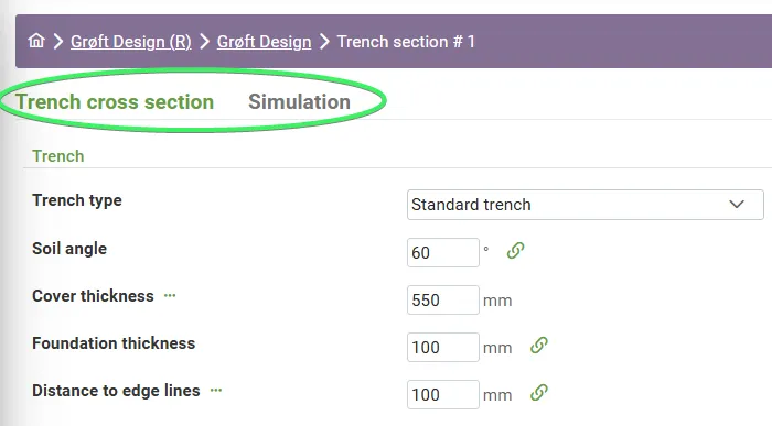
Section titled “Improved User Interface to Support Your Workflow”With the growing number of features in Grøft Design® and to prepare for upcoming features, we have split the familiar Trench Section in two new tabs.
- Trench Cross-Section Tab focused on trench geometry, allowing users to add cables and other components.
- Simulation Tab designed for scenario-based simulations, enabling users to construct and analyse different trench configurations.
This will better support your workflow. First you focus on drawing the physical trench cross-section with cables, pipes, virtual sensors and all the other components you can add in Grøft Design®. Then you can move on to the Simulation Tab, to define the simulations with different scenarios.
Scenarios is also a new concept that is introduced in this release that simplifies conducting multiple studies on the trench cross-section.
The tutorial getting started shows the new workflow in more detail.
Simulate Variable Load over Time
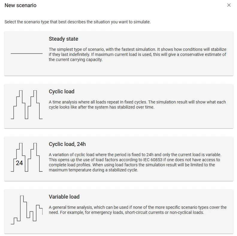
Section titled “Simulate Variable Load over Time”Introduced the module which enables the calculation of the dynamic current rating for complex cable arrangements and variable loading patterns. For the time-varying load defined by the user, the software results with a transient electro-thermal response. Among others, the following functionalities are featured:
- Modelling of cyclic load and variable load, accommodating different simulation needs.
- Transient analysis considering the load factor.
- Analysing the emergency loads up to the specified max. temperature.
- Constant or variable in-time temperature on the ground surface
- Modelling of the load patterns/time series directly in the software, or uploaded as an xlsx or csv data file.
The tutorial Simulation options, provides a more detailed overview of the new simulation methods.
This feature is only available for Beta-users.
Cloud-based Simulation
Section titled “Cloud-based Simulation”- Added support for cloud-based simulations, for increased simulation capacity and scalability.
Trench Report
Section titled “Trench Report”- The description of the trench-section is now available in the exported Trench-report.
Release 2024 September
Section titled “Release 2024 September”Support for Cables in Metal Pipes
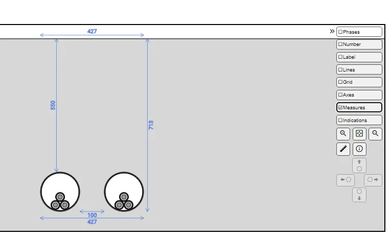
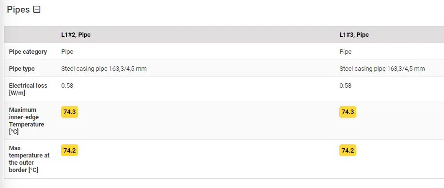
Section titled “Support for Cables in Metal Pipes”Grøft Design® has included the feature to calculate the effects of cables in metal pipes. It calculates the induction and heating of metallic pipes.
Release 2024 August
Section titled “Release 2024 August”Fix Display of Insulation Loss
Section titled “Fix Display of Insulation Loss”For multi core cables, insulation loss was calculated correctly, but displayed incorrectly in the results. This has no impact on the simulation itself, but after this fix, the insulation and total losses presented in the results might decrease somewhat for trenches that include multi core HV cables.
Improvements to Touch screens
Section titled “Improvements to Touch screens”Some usability improvements have been made for devices that use touch input rather than mouse - such as phones and tablets.
Release 2024 June 2
Section titled “Release 2024 June 2”Support for Ampacity Calculation
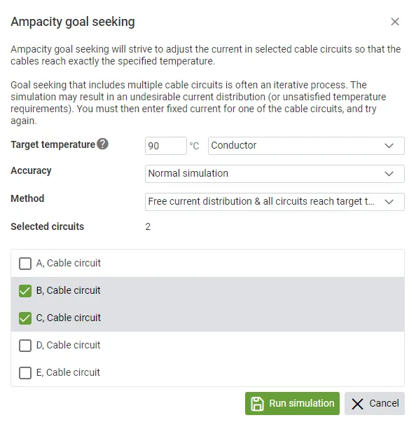
Section titled “Support for Ampacity Calculation”Ampacity calculations are now supported as an alternative to fixed current simulations. This feature allows you to quickly find cable circuit currents that result in a specified target temperature.
You can select one or multiple cable circuits, but should be aware that the exact specified temperature must be reached for all cable circuits. This is often what you want, but sometimes it’s impossible to achieve - e.g. because one of the cables may always exceed the target temperature when another one satisfies the target temperature. Thus, for more complicated cases, goal seeking is an iterative process where you might need to enter a fixed current for some cable circuit and then rerun for the remaining cable circuits.
Cables in Water Filled Pipes
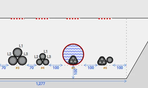
Section titled “Cables in Water Filled Pipes”Cable pipes (ducts) can now be configured with water as fill material. They will then be assigned a thermal resistivity based on IEC 60287-2-1, which is a decent approximation, and will work sufficiently well in most cases. The IEC formula assumes that the cable is centered in the pipe, but moving the cable to the bottom of the pipe has limited impact on the result since conduction is the primary means of heat transfer.
Individual Baselines
Section titled “Individual Baselines”When modelling separate trenches on a sloped terrain, the lowest point on any trench was previously used to determine a single baseline. Cover thickness for each trench was then relative to this baseline - resulting in too much actual cover for trenches on elevated ground. This has now been changed so that an individual baseline is calculated for each isolated trench.
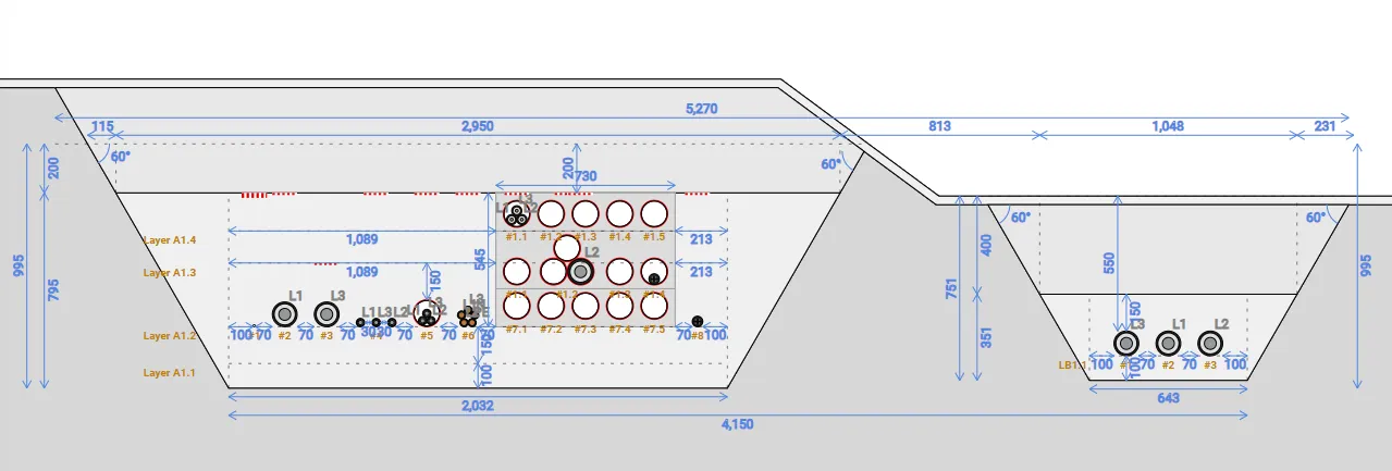
Extensions to the Excel-file for Simulation Details
Section titled “Extensions to the Excel-file for Simulation Details”The Excel-file for simulation details has been extended with more data. This includes thermal resistivities and detailed information about cable layers and pipes.
Release 2024 June
Section titled “Release 2024 June”Improved result images
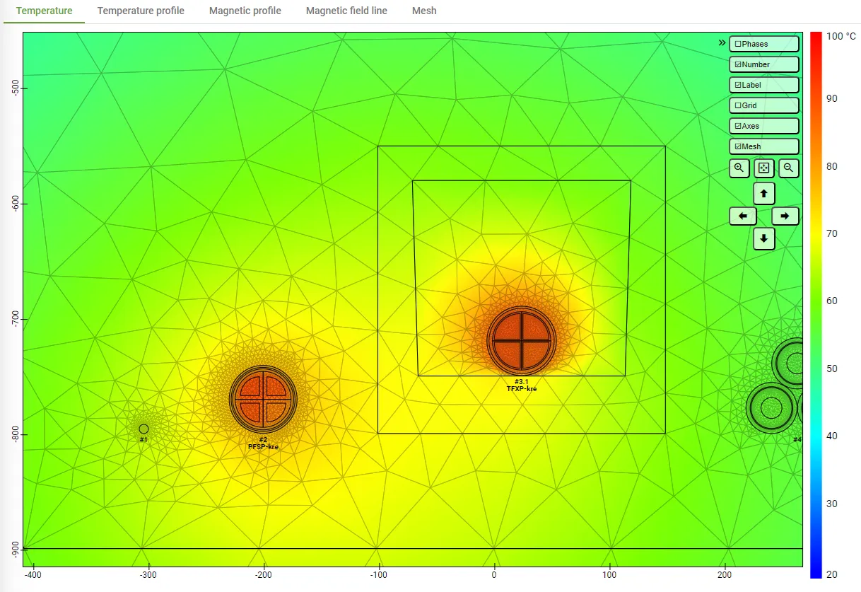
Section titled “Improved result images”Result images are now rendered dynamically while you view them, which results in a few significant improvements:
- You can pan and zoom in and out.
- You can hover the mouse pointer at a location and see the exact temperature at that spot.
- You can select objects in the image, and see their results highlighted in the tables below - and vice versa.
- You can show or hide optional visualization layers or result sets.
- Image resolution is higher.
- Text in an image is no longer hard coded to the language that the simulation was run in.
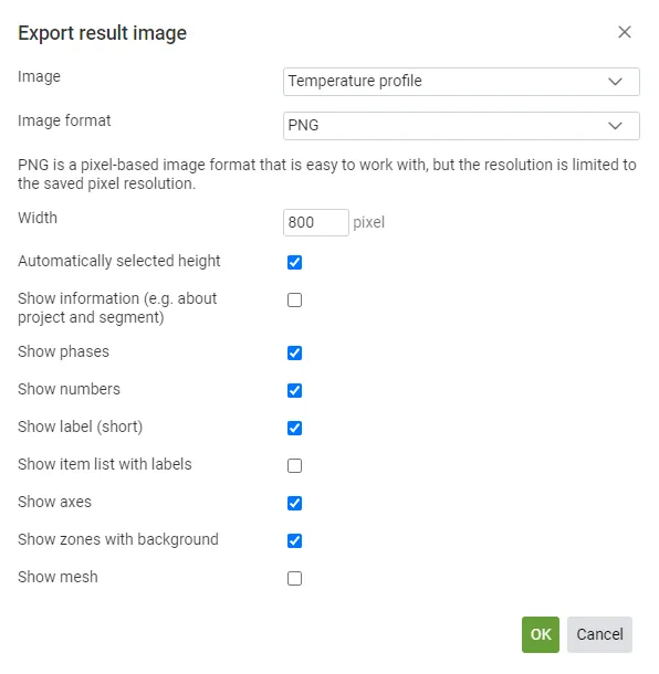
Export Result Images
Section titled “Export Result Images”Result images can now be downloaded as SVG or PNG files, in the same manner as the geometry image.
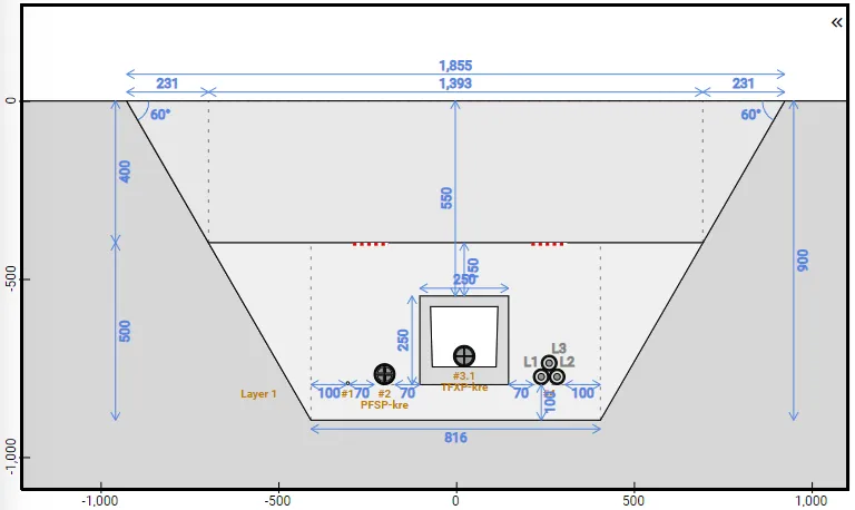
Enhancements for the Geometry Image
Section titled “Enhancements for the Geometry Image”You must now click the geometry image in order to activate mouse wheel zooming. This will prevent unintentional zooming while scrolling the page.
X- and Y-axes can now optionally be shown.
The informational boxes & control buttons on the right hand side of the geometry image can now be collapsed.
Live Temperature Display During Simulations
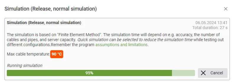
Section titled “Live Temperature Display During Simulations”When running a simulation, the progress dialog will now show the live temperature. This slightly improves progress feedback, and also provides an early indication about simulations that will reach too high temperatures and can be aborted.
Support for Multiple Languages in Reports
Section titled “Support for Multiple Languages in Reports”You can now select language when downloading a report. This is most useful if you work on a project in your local language but want to send the report to a third party that does not speak your language.
Minor Adjustment to Cable Capacitance Formula, now Compliant with IEC Standards
Section titled “Minor Adjustment to Cable Capacitance Formula, now Compliant with IEC Standards”The expression for capacitance of cables in Grøft Design® did not consider the thickness of conductor screen. It has now been changed to comply with the approach introduced by the IEC 60287 standard. It leads, however, to slight increase of dielectric losses of insulation. With reference to Technical Brochure 880 by CIGRE, for reference 33 kV cable land cable (CASE 4) the total heat loss in cable increases by 0.03%. For reference 400kV LPOF Cable (CASE 5) the total heat loss in cable increases by 0.56 %. Dielectric losses are voltage dependent and according to IEC 60287 should be taken into account for nominal system voltage equal to and above 220 kV (for XLPE insulated cables).
Modified Thermal Resistivity for PVC Pipes, now Compliant with IEC Standards
Section titled “Modified Thermal Resistivity for PVC Pipes, now Compliant with IEC Standards”The thermal resistivity for PVC in pipes was previously 8 mK/W, and has been changed to 6 mK/W, as recommended by IEC. Typically, this will only have a minor impact on the result. But in some cases, it might affect the results with as much as one degree Celsius.
Enabled Horizontal and Vertical Adjustments for Aerial Objects
Section titled “Enabled Horizontal and Vertical Adjustments for Aerial Objects”The limitation of not allowing positional adjustments of objects in air has been lifted. This means that you can e.g. center a cable in an air filled pipe, or place a cable in an air filled cable trough on a “pretended shelf”.
Updated Help text for Thermal Resistivity with Relevant Example Values
Section titled “Updated Help text for Thermal Resistivity with Relevant Example Values”The guidance text for thermal resistance has been extended and improved with guiding values from CIGRE, IEC and research/measurements done by SINTEF Energy Research and Norwegian University of Life Sciences.
Extended Cable Results
Section titled “Extended Cable Results”Simulation results now include maximum surface temperature for all cables. For multi core cables with a dedicated screen per core, the screen current results are now shown per core.
Excel Export with Detailed Simulation Results
Section titled “Excel Export with Detailed Simulation Results”An Excel file can now be downloaded from the results page. This file includes the magnetic field data from the previous Excel file, plus detailed results for cables, pipes etc.
Larger “hotspot” for Hovering, Clicking and Dragging Small Objects
Section titled “Larger “hotspot” for Hovering, Clicking and Dragging Small Objects”Selecting or dragging objects like sensors and ground wires in the geometry image can be difficult due to their small size. This has been improved by allowing a larger “hotspot” area around them.
Release 2024 February
Section titled “Release 2024 February”Cable Circuits
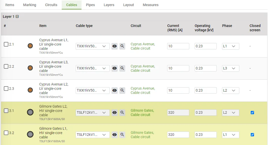
Section titled “Cable Circuits”Cable groups and multi core cables used to implicitly define a circuit, and Multiple Cables per Phase was a separate concept. This release introduces cable circuits as streamlined and configurable entities. Benefits include:
- Identical handling for all circuits (Single and Multi Cables per Phase).
- Flexibility in how cables are mapped to circuits.
- Improved clarity and separation between cable and cable circuit configuration and results.
Revised tabs
Section titled “Revised tabs”The tabs on the configuration page have been redefined for improved clarity and usefulness.
Release 2023 December
Section titled “Release 2023 December”Change the System Frequency
Section titled “Change the System Frequency”With the new update you can change the system frequency from the dropdown in on the trench segment overview page.
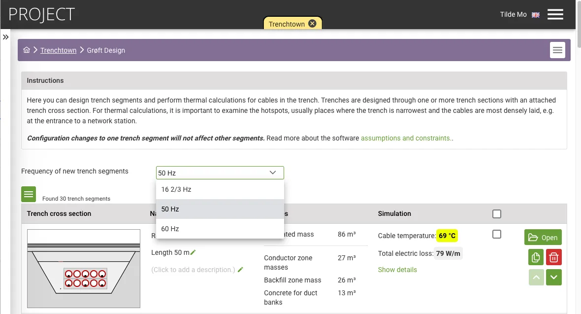
Different frequencies within the same trench section are not supported.
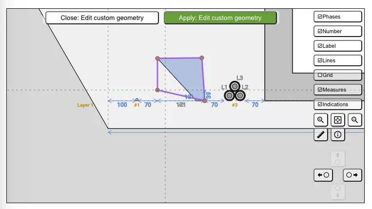
Custom Objects
Section titled “Custom Objects”With custom object you can quickly define your own object that is in the trench. Please note that metallic materials are not supported for now.
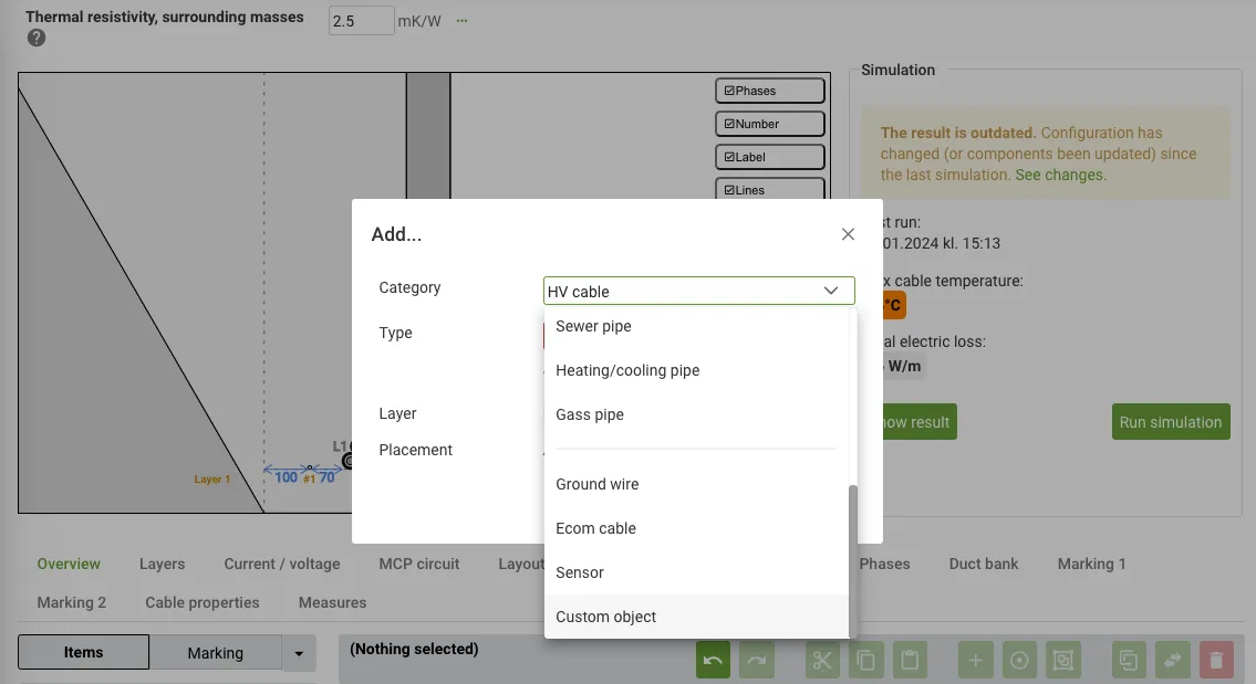
Choose among different geometries or create your own.
Release 2023 November
Section titled “Release 2023 November”Simulate Drying Out of Masses
Section titled “Simulate Drying Out of Masses”Grøft Design® now includes an advanced capability to simulate the drying out of masses. This feature allows for a comprehensive understanding of how masses within the trench interact and dry out over time, offering a more accurate representation of real-world conditions.

The dry out functionality is a step function that depends on the temperature for the trench zones. With that you specify how the thermal resistivity of the masses changes with changing temperature.
The figure below is an example of how you can set the thermal resistivity to 1mK/W up to 60°C in the conductor zone. Above 60°C these masses start to dry out so you would increase the thermal resistivity to 2mK/W.
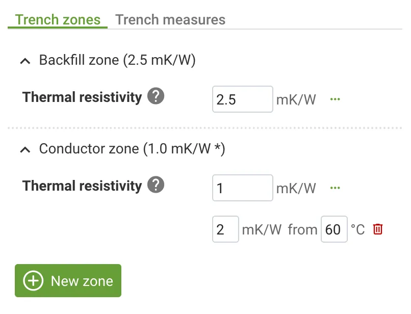
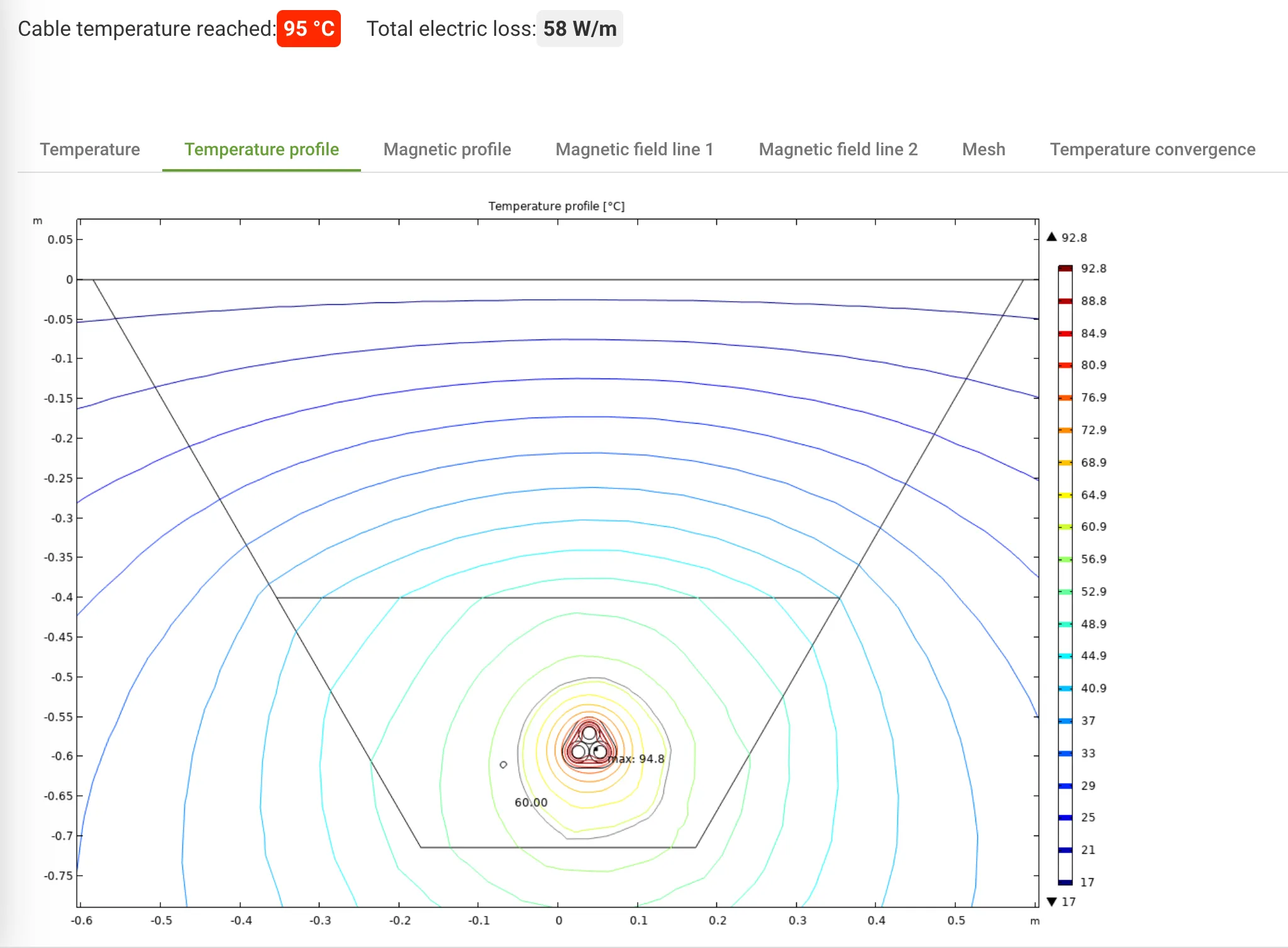
Notice the highlighted temperature line for the dry out zone at 60°C. It is only applicable for the trench zones with defined dry out zones.
Report Updates and Output Layout Enhancements
Section titled “Report Updates and Output Layout Enhancements”We’ve improved and updated the reporting functionality within Grøft Design®. Enhancements to the report layouts provide a clearer presentation of data, making it easier to interpret and analyze results.

Reports for Selected Trench Sections
Section titled “Reports for Selected Trench Sections”With the new update, you can now generate reports specifically for selected trench sections. This feature offers a more customized approach, enabling you to focus on specific sections of interest and extract comprehensive reports accordingly.
Export Geometry image as SVG or PNG
Section titled “Export Geometry image as SVG or PNG”The export image function is more flexible. In addition to SVG-format you can now export the trench section image as PNG. Select if the image should be sized automatically or manually override the height, and toggle project information in the image.
Release 2023 September
Section titled “Release 2023 September”Document the Cable
Section titled “Document the Cable”In the Cable Designer you can add documentation for your cables. With this release you can also add links to online documentation.
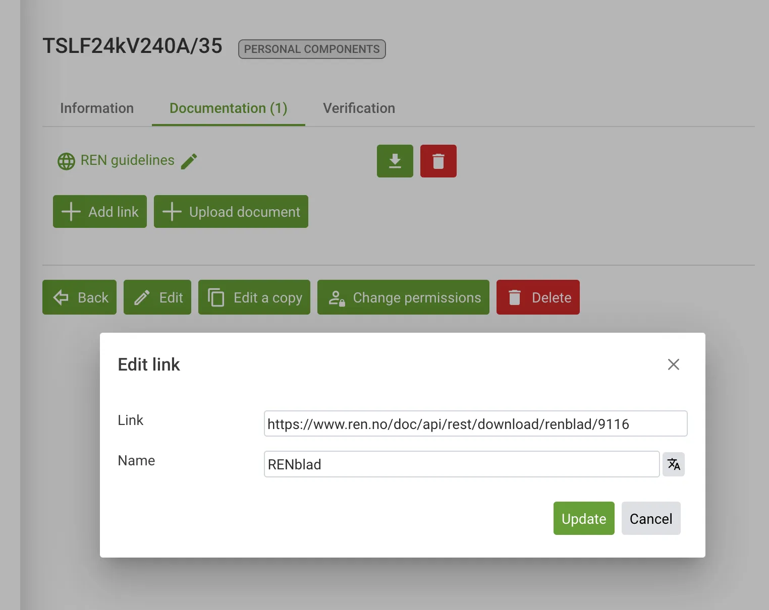
This is particularly useful if you have documentation that you need to restrict access to by linking to your own content management system.
Verify the Cable
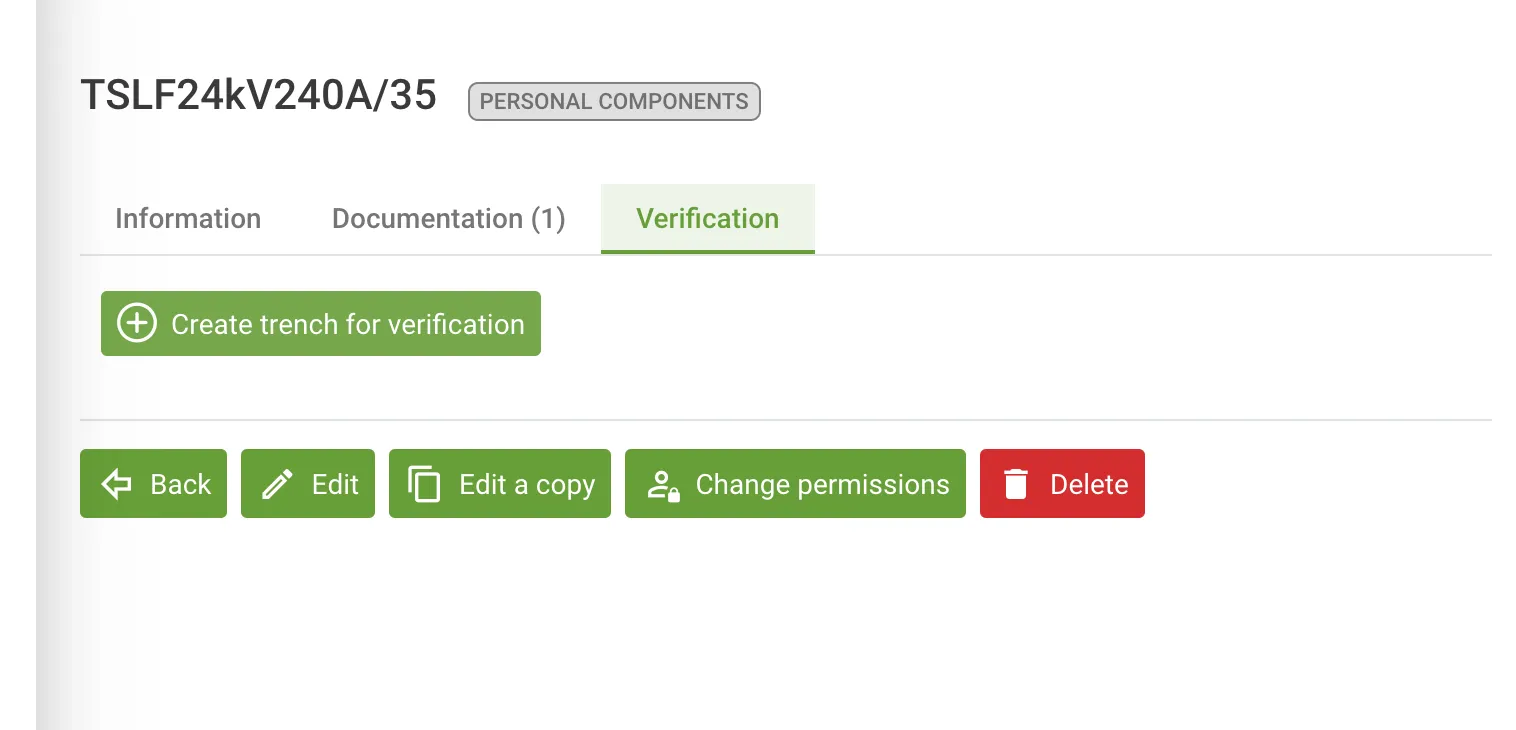
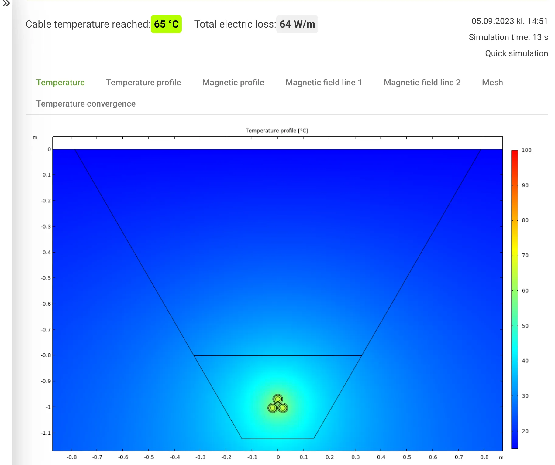
Section titled “Verify the Cable”When designing a cable it’s important to verify the design. Under the verification tab in the Cable Designer you can create simulations that verify the cable temperature for a given current.
Create trench for verification
Set a target temperature for the trench
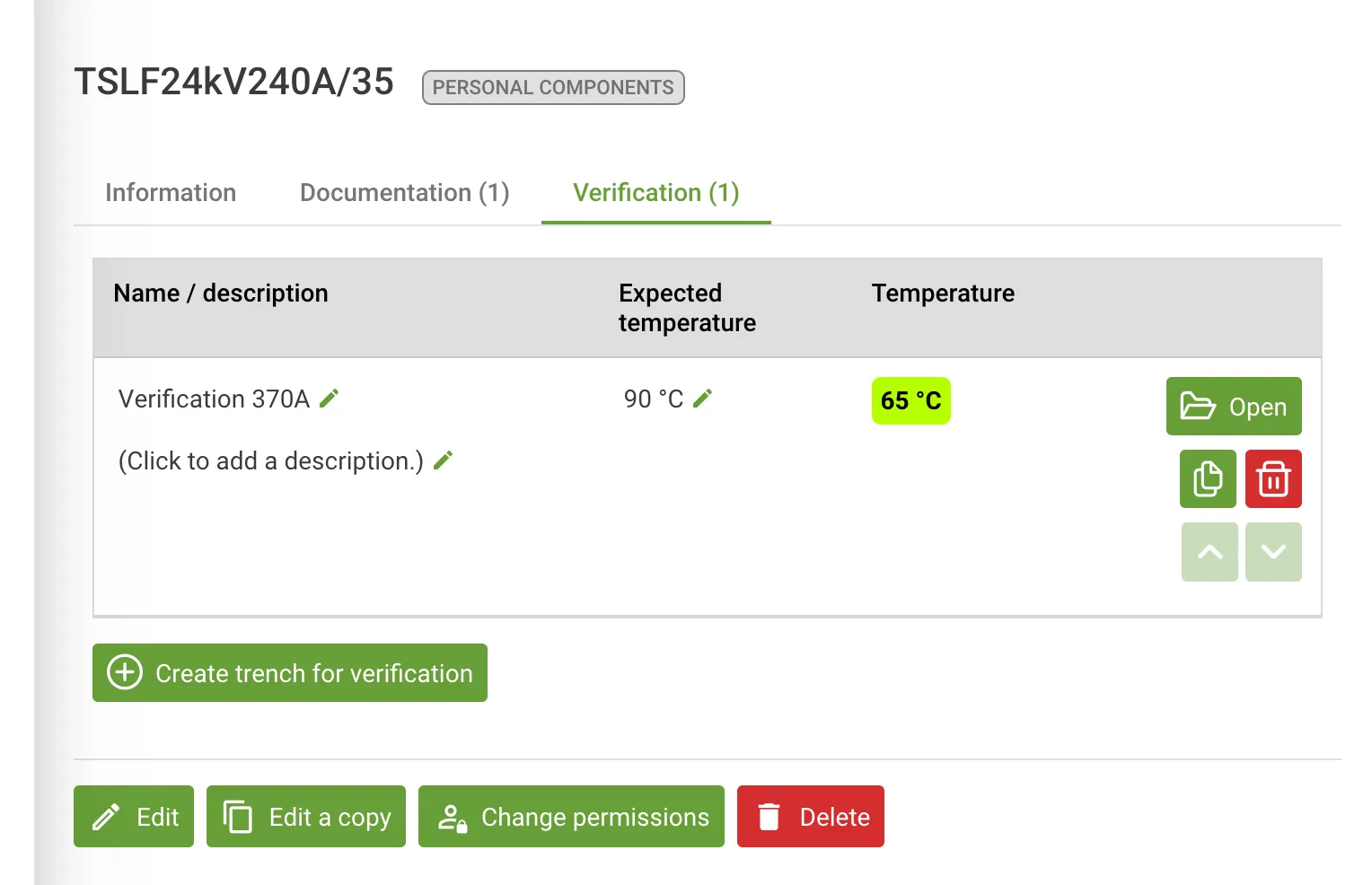
View the temperature report
Component Language Improvements
Section titled “Component Language Improvements”When you create new components you might want to share those components with other users. If the user has a different language you can now translate the component directly in the Component Designer.
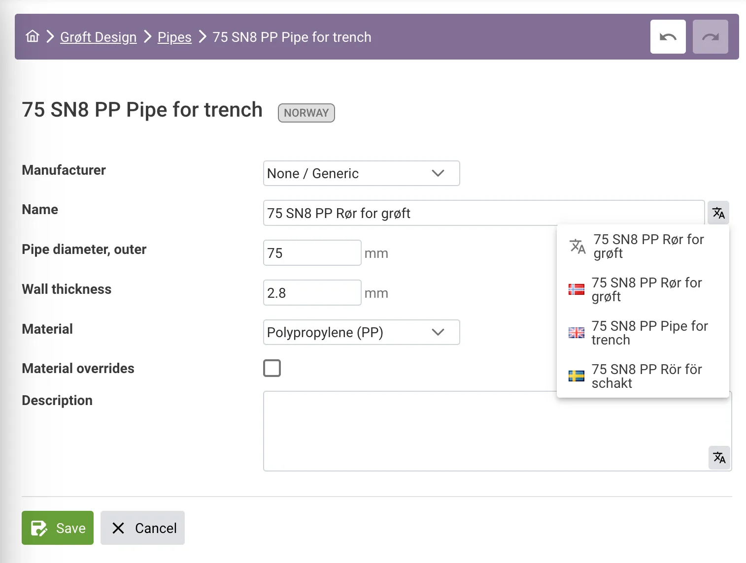
All components have a standard language. In addition they can have an optional translation.
The standard language of the component is decided by the component owner. REN should probably default to English, and always add translation to Norwegian and other supported languages.
If you publish a component with translation, users will view the translation if it is in their language. If not it will fall back to default. Grøft Design® will look at the active language, not at the other languages the user might have.
Release 2019 December
Section titled “Release 2019 December”Grøft Design® is released to the Norwegian market 🎉