Heat Losses In a Cable
Under the operating conditions, several sources of heat are present in the power cable. These are dependent on the construction of the cable and the installation conditions. Both, current and voltage dependent heat losses account for the net heat loss in the cable. A short description of each is given below. For cable rating calculations heat losses are expressed in W/m.
Conductor Losses
The primary losses of power cables are the ohmic losses of the conductor, denoted as WC. These losses increase as a function of the square of the current flowing through the conductor and the electrical resistance of the conductor (I2 x R). Furthermore, as the alternating current typically has a frequency of 50-60 Hz, the distribution of current in the conductor is not uniform, due to skin and proximity effects. This in turn results in the increase of losses which are additionally elevated in the presence of the magnetic field from parrallel cable installation. The following design choices of the conductor must be made for rating of the cable installation:
Conductor Cross-Section and Material
Heat loss is proportional to resistance, therefore current carrying capacity of the cable increases with larger cross-section conductors 1 .Typically, aluminium (AL) or copper (CU) conductors are used, with the standard size dedicated to electrical grids ranging from 25 to 3200 mm².
Conductor Type:
Conductors are most often composed of stranded wires, twisted longitudinally (Cable example 1 and 2). The cross section of such stranded conductor is however not homogeneous, as in case of a solid conductor. Several manufacturing techniques are utilized by the cable producers to increase the effective cross-section of stranded conductor, such as choice of the adequate size of wires and the degree of its compression. The resulting resistances of the conductors is standardized by the IEC for given type of conductor, cross section and material 1. This data is also given by the producer in the cable specification in the datasheet. In Grøft Design® the effective resistance of the conductor is assigned automatically for given dimensions and type of conductor. Users may change the resistance for non-standardized cable design.
For homogeneous conductor cross-section, the rating of the power cable that operates at alternating current decreases due to the skin and proximity effects. These effect, however, can be suppressed for the conductors divided into electrically separated segments. For conductors that implement the separation of each wire, the skin and proximity effects are effectively excluded in the scale of whole section of conductor, since current flow individually through each wire. This type of conductor is called Milliken (cable example 3) and is commonly applied in power distribution grid. In the Grøft Design® software all types of mentioned conductor types can be modelled with possibility of a modification of individual parameters and factors specified by IEC standards.
| Cable example 1 | Cable example 2 | Cable example 3 |
|---|---|---|
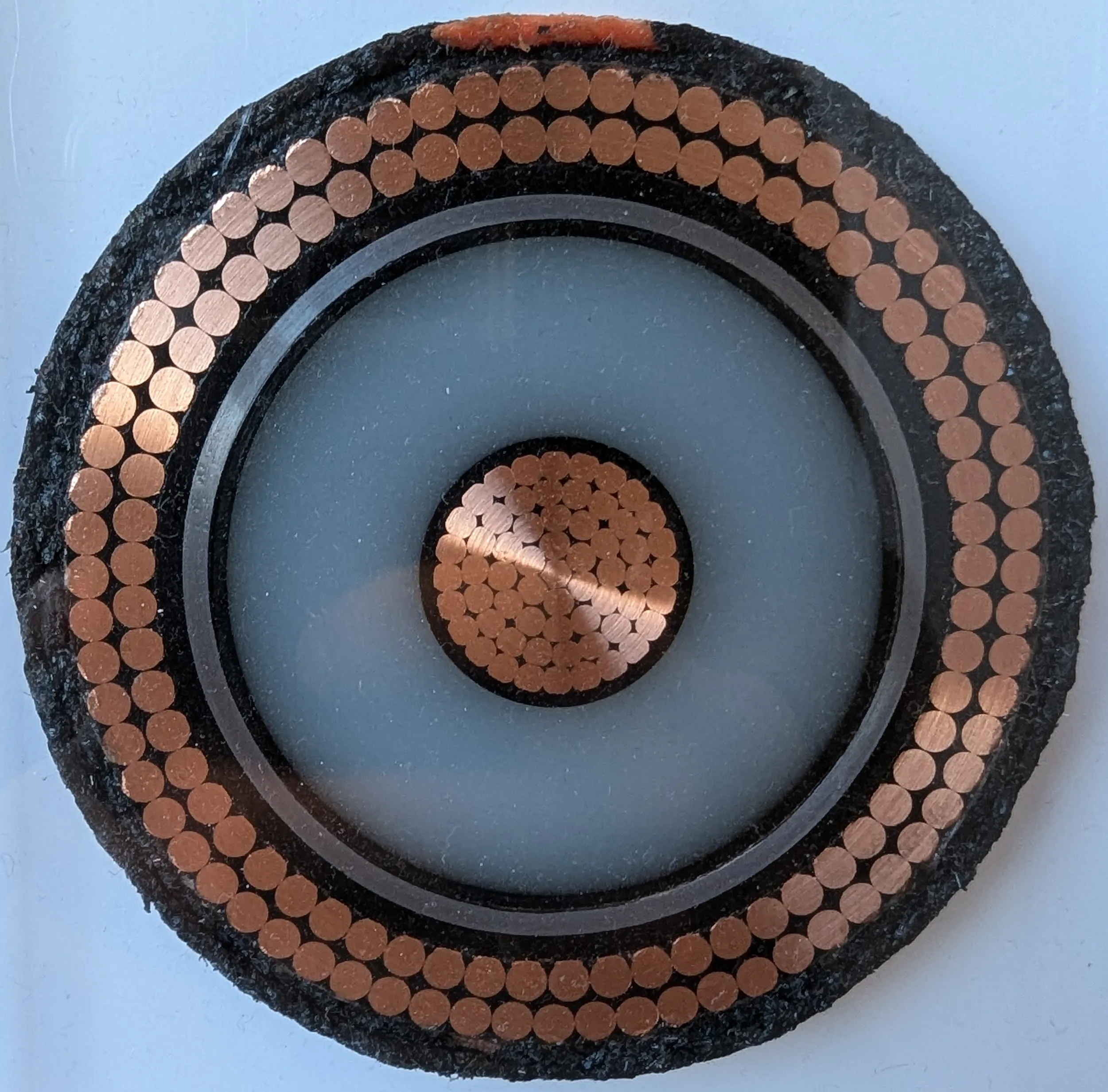 | 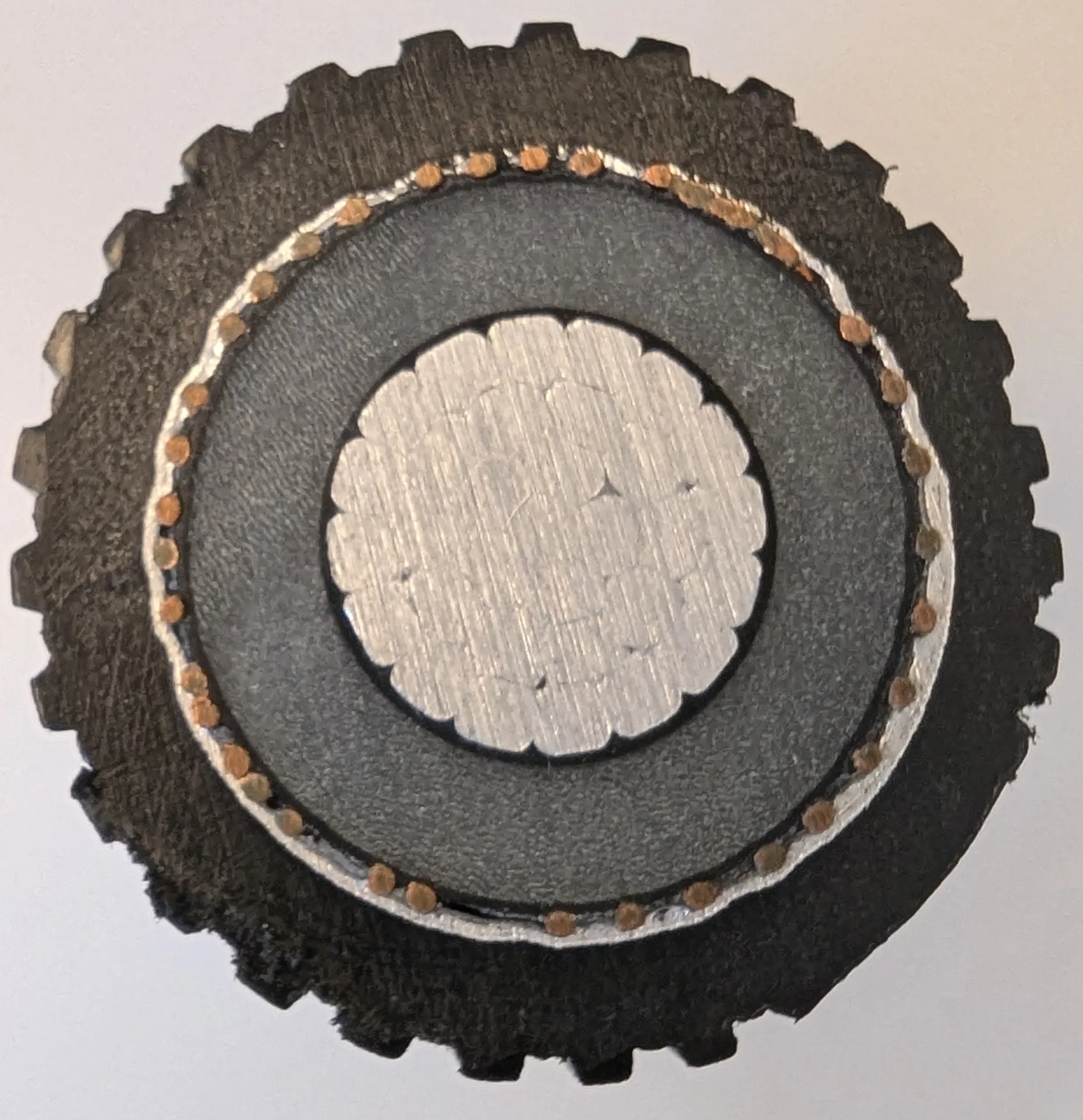 | 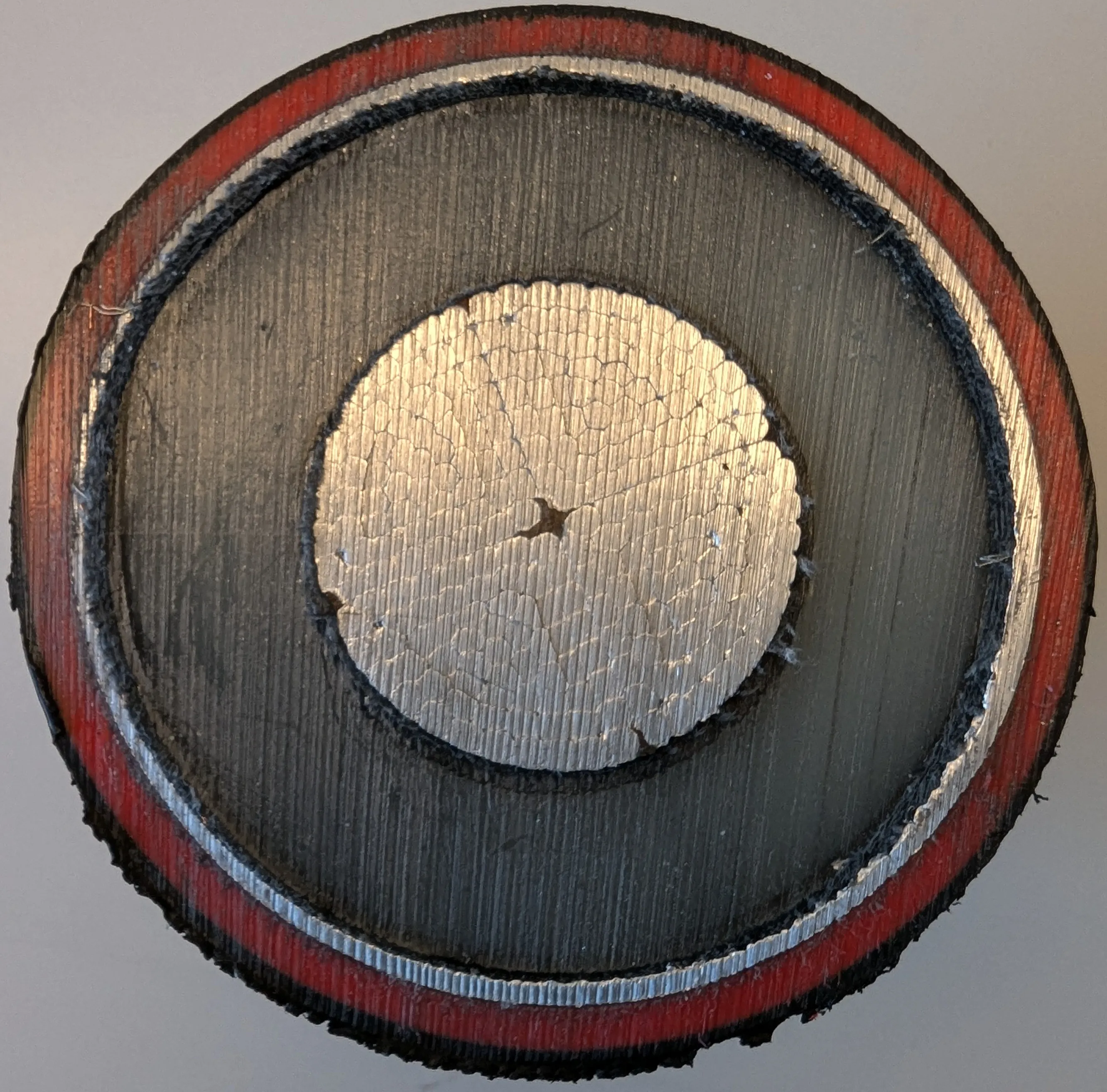 |
| 170 kV 400 mm2 CU | 24 kV 240 mm2 Al | 170 kV 1600 mm2 Al |
Sheath/Screen Heat Losses
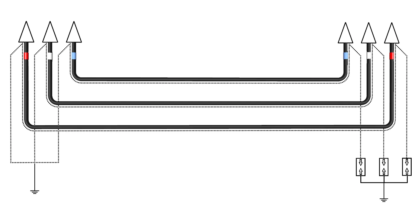
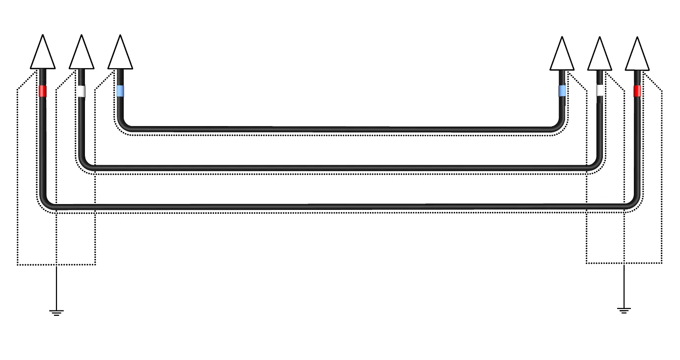
Increased temperature of the sheath hinders the dissipation of heat from the conductor, leading to decrease of cable rating. The degree of the heat loss in metallic sheaths is dependent on the cross section of the sheath and bonding type, i.e. grounding. Eddy current losses in sheath are present regardless of the bonding type and are usually not of a major concern, as in case of a single-point bonded installations. For solid bonding of the sheath/screen, e.g. two-point bonded systems, the presence of circulating currents elevates the net heat loss in cable considerably.
For single-point bonded system the absence of circulating currents allows for higher current capacity through the conductor. But this kind of installation may be vulnerable to partial discharges due to accumulated voltage at the non-bonded end, therefore it can be applied only on a cable in limited distances. For a solid bonded system this standing voltage is often not a design criterium. A special bonding arrangement, i.e. cross-bonding, can suppress the circulating current, and even exclude them in case of well-balanced system, however the caution must be put for design of such installation as the voltage will be accumulated at the point of cross-bonding. Grøft Design® support analysis of cable for both single- and solid bonding. The design of cross-bonded installations and installations composed of multiple geometrically different cable layouts will be developed as a part of the INCA project.
| Singel-Point Bonding | Solid Bonding |
|---|---|
 |  |
Armour Heat Losses
Heat losses in the armour follow the same principles as the previously mentioned metallic sheath losses. Most armoured cables are constructed using magnetic steel wires or tape, in which case hysteresis losses and twisting effect must also be accounted for. The calculation of the armoured cables is not yet supported by the Grøft Design® software.
Dielectric Heat Losses
The coaxial formation of two conductors which have an electric potential difference, i.e. conductor and metallic sheath, separated with insulation, makes cable a cylindrical capacitor. Alternating current creates time-varying electromagnetic field that will lead to cyclic charging and discharging of the formed capacitor. This change of dielectrics polarization results in the release of the energy in the form of dielectric losses, i.e. heat. Dielectric losses are voltage and insulating material dependent.
Heat Losses Caused by The Charging Current
The charging current produced by the cable capacitance generates ohmic losses in the cable that are present any time the cable is energized. These are usually neglected in cable rating calculations2 and Grøft Design® does not account for these losses. The increase of the charging current reduces the supply current corrspondingly. For example, 132 kV XLPE 630 R cable installation operating at frequency of 50 Hz, and for the cable insulation capacitance of 0.211 μF/km, the charging current would be equal to 5.05 A/km.