Introduction in Cable Planning
Planning cable projects requires a deep understanding of the factors that influence cable performance and how to adjust variable values and layout to meet project requirements. This tutorial provides an introduction to the key aspects of cable planning.
For further reading on cable planning/rating, the following literature is recommended:
- A Guide for Rating Calculations of Insulated Cables by Cigre TB 640.
- Rating of Electric Power Cables by George J. Anders.
- The Calculation of the Temperature Rise and Load Capability of Cable Systems by J. H. Neher, M. H. McGrath
- RENblad 9200 “Prosjektering av kabel” (Only available in Norwegian) by REN AS
TB 640 is based on IEC 60287, which covers the continuous current rating of cables (100% load factor), and IEC 60853, which addresses cyclic and emergency current ratings.
There are more information on heat losses in a cables can be found on this page
Cable Ampacity
Cable ampacity, or the maximum amount of electrical current a cable can carry, depends on various factors, including the cable’s physical properties, its environment, and the configuration of the screen and phase sequence. The following are key factors that affect the cable ampacity:
- Conductor cross-section and material: Larger cross-sections and materials with lower resistivity (e.g., copper over aluminum) lead to higher ampacity.
- Insulation material: The type of insulation affects the cable’s maximum operating temperature and ampacity. Common insulation materials include:
- PVC: 70°C
- HDPE: 80°C
- XLPE (PEX): 90°C
- HEPR: 105°C
- Thermal resistivity (mK/W) of surrounding materials: Includes the masses in the conductor zone, backfill zone, and surrounding masses.
- Ground temperature
- Depth of installation
- Crossing infrastructure and external heat sources: Such as the heat from nearby cables.
- Drying out of surrounding soil or materials
- Installation method: Whether the cable is in ducts, pipes or directly buried affects heat dissipation.
- Screen configuration and overall cable design
Installation Method
The method used to install cables has a significant impact on their performance, lifespan, and safety. The choice of installation method depends on factors like the environment, the type of cable, mechanical protection needs, and heat dissipation requirements. Below are common installation methods for power cables:
Direct Burial
In direct burial, cables are laid directly in trenches in the ground, surrounded by sand or other thermal backfill materials. This method is cost-effective and offers good heat dissipation due to direct contact with the surrounding soil.
Pipes and Duct Banks
Cables that are run through plastic or metal pipes/ducts banks can be buried underground or mounted on surfaces. This provides additional protection from external damage and environmental factors. While heat dissipation is less efficient compared to direct burial, ducts banks and pipes provide easier access for cable replacement.
Operating Conditions
Ambient temperature, soil thermal characteristics, and laying depth all influence cable ampacity. These factors should be carefully selected for each project. IEC 60287-3-1 provides guidelines on recommended values in different regions/countries:
- Soil thermal resistivity (mK/W): Accurate knowledge of soil resistivity is crucial for determining ampacity.
- Depth of installation: Shallow installations allow better heat dissipation, while deeper installations can reduce ampacity.
- Air ambient temperature
All of these values greatly impact the cable ampacity and must be selected specifically for each cable project.
Conductor Cross-Section and Material
Typically, aluminum (AL) or copper (CU) is used, with conductor sizes ranging from 25 to 3200 mm² in electrical grids. Larger cross-sections reduce resistance and heat loss, increasing ampacity. Copper further increases ampacity but comes at a higher cost compared to aluminum.
Insulation Material
When a current is applied a cable, the cable heats up. Once the maximum allowable temperature is reached, the cable has reached its ampacity rating. Materials with higher temperature limits, like XLPE (90°C), allow for greater ampacity then for example PVC (70°C). XLPE is the most common material for new cables in electrical grids.
Ampacity Given in Datasheets
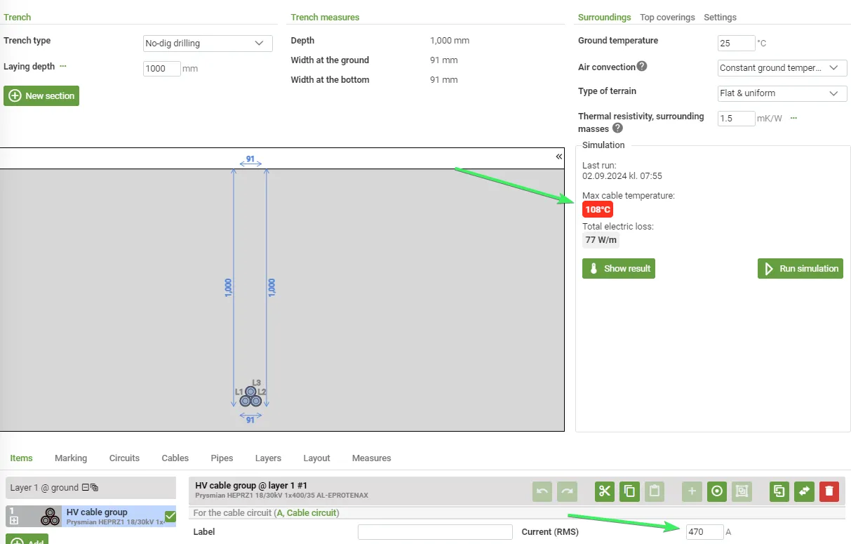
Cable datasheets provide ampacity ratings based on specific conditions such as burial depth, thermal resistivity, and ambient temperature. For example, a HEPRZ1 18/30kV 1x400/35mm2 cable from Prysmian Group has an ampacity of 470A at 105°C under the given conditions in the datasheet. When the datasheet is verified in Grøft Design®, results may vary slightly but should be close to the datasheet values. Altering conditions from those in the datasheet will change the cable’s ampacity.
| Source | Ampacity | Conductor Temperature | Prerequisites |
|---|---|---|---|
| Datasheet | 470A | 105°C | Three cables in a trefoil arrangement, directly buried at 1m, soil at 25°C, 1.5mK/W. |
| Verification of datasheet in Grøft Design® | 470A | 108°C | Three cables in a trefoil arrangement, directly buried at 1m, soil at 25°C, 1.5 mK/W. |
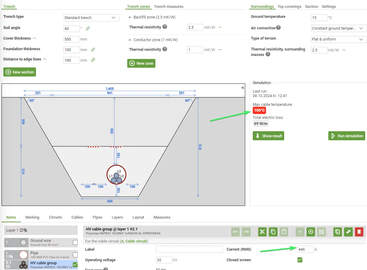
| Calculation in Grøft Design® | 446A | 105°C | Three cables in a 160 mm pipe in a trefoil arrangement, buried at 0,6m, soil at 15°C, 2.5mK/W. Conductor zone at 1.0mK/W |
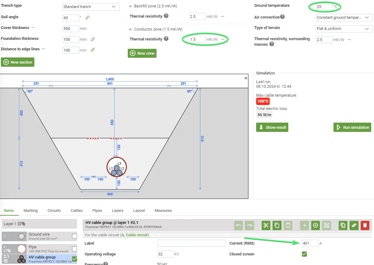
| Calculation in Grøft Design® | 401A | 105°C | Three cables in a 160 mm pipe in a trefoil arrangement, buried at 0,6m, soil at 25°C, 2.5mK/W. Conductor zone at 1.5mK/W |
Datasheet and Verification


The Examples of Altering Conditions
Placing the cable in a pipe:

Increasing the thermal resistivity in the conductor zone and raising the ground temperature:
