Shield/Sheath Bonding System
Grøft Design® supports different types of cable shield/sheath bonding arrangements:
- Solid Bonding
- Single-Point Bonding
- Cross Bonding
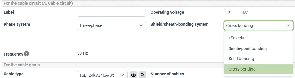
To change between the different bonding arrangements, select the cable in the “Trench Cross-Section” tab and use the drop-down button “Shield/Sheath Bonding System.”
Solid bonding is commonly used in low and medium voltage cable systems. While it can also be applied to high voltage cables, large currents significantly increase shield/screen currents, leading to higher thermal losses and reduced ampacity.
To mitigate these losses and improve current-carrying capacity, many high voltage cable systems instead utilize cross bonding or single-point bonding configurations.
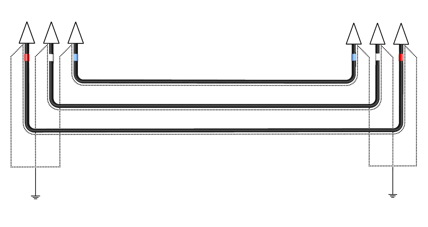
Solid Bonding
In a solid bonding setup, the cable shield or screen is electrically connected and grounded at both ends. This allows circulating currents to flow through the shield, generating heat and energy losses that reduce the cable’s ampacity.
Advantages
- Very low screen-to-earth voltage at cable ends
- Simple installation
- No additional maintenance required
Disadvantages
- Circulating currents cause additional heating and losses
- Reduced ampacity may require cables with larger cross-sections
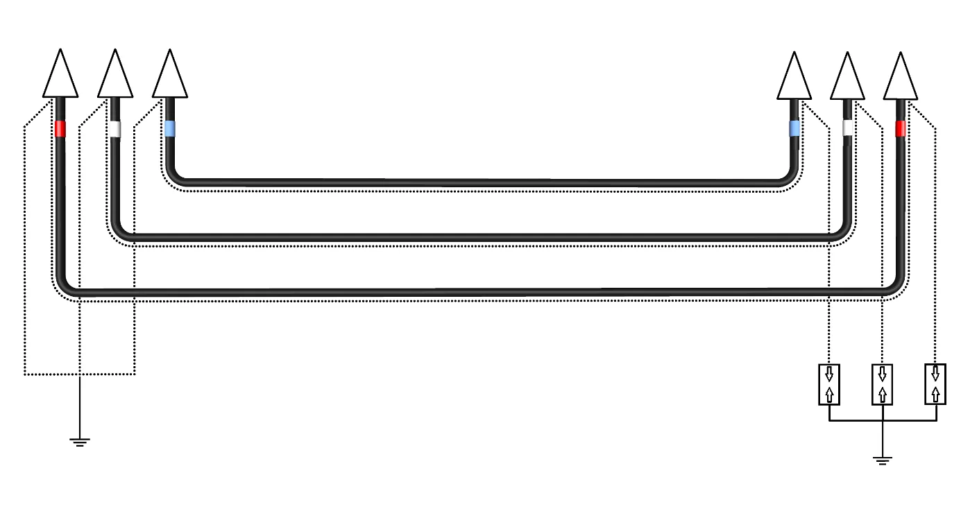
Single-Point Bonding
In this configuration, the cable shield or screen is grounded at one end and left floating at the other. This prevents circulating currents but results in a standing voltage at the ungrounded end.
Voltage Build-Up Factors
- Cable geometry
- Load current in the conductors
- Distance from the grounded point
Due to voltage buildup, cable length is limited. A Sheath Voltage Limiter (SVL) is typically required at the floating end to protect against overvoltages. An Earth Continuity Conductor (ECC) is also usually installed to provide a reliable return path for fault currents.
According to CIGRÉ Technical Brochure 797, “Sheath Bonding Systems of AC Transmission Cables”, it is recommended to:
- Transpose the ECC at the midpoint of the cable section
- Install it close to the conductors to minimize induced voltages and improve system performance
Advantages
- No circulating currents, only eddy currents
- No heating/losses in the screen caused by circulating currents
Disadvantages
- Standing voltage at one end
- Not suitable for long cable runs
- Usually requires an SVL at one cable end
- Usually requires installation of an ECC along the cable
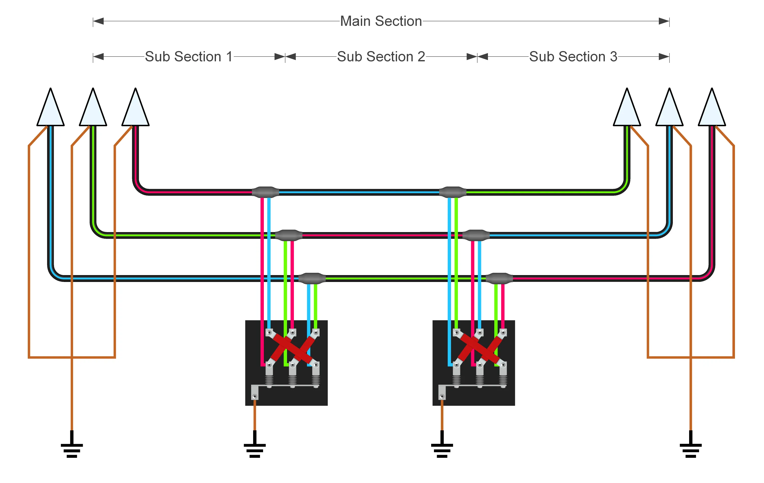
Cross Bonding
In a cross bonding configuration, the cable shield or screen is segmented at regular intervals using cross-bonding joints. At each joint, the screens are interchanged between the phase conductors to balance induced voltages across the cable sections.
Under ideal conditions, the induced voltages in the three phases are offset by 120°, and when combined, they effectively cancel each other out—resulting in minimal or no circulating currents.
For optimal performance, the cable should be divided into three sections of equal length. If section lengths vary, voltage cancellation will be incomplete, and residual circulating currents may occur.
Advantages
- No circulating currents (in ideal conditions), only eddy currents
- No standing voltage at the cable ends (in ideal conditions)
- No heating/losses in the screen caused by circulating currents
- Suitable for long cable lengths, but the section lengths are limited by the standing voltage at the point where the screens are transponded in the link box.
Disadvantages
- Complex installation
- Requires regular maintenance and monitoring
- Needs three or more cable sections (e.g., 3, 6, 9, 12…)
- Challenging to achieve equal section lengths in practice